Glenn’s Computer Museum |
| Home | New | Old Military | Later Military | Analog Stuff | IBM Stuff | S/3 Mod 6 | S/32 | Components | Encryption | Misc | B61 |
change log |
contact me |
![]()
Glenn’s Computer Museum |
| Home | New | Old Military | Later Military | Analog Stuff | IBM Stuff | S/3 Mod 6 | S/32 | Components | Encryption | Misc | B61 |
change log |
contact me |
![]()


It turns out that the famous Norden bombsight was not only U.S. bombsight of World War II. The first bombsight accepted by the Government was the Sperry S-1 that was developed in the 1930's. It was designated as "standard" equipment in March 1941 and was used in some U.S. Army Air Forces bombers early in World War II, primarily B-24 Liberators. However, all contracts for production of the Sperry sight were canceled in late 1943. Many claim that the Sperry S-1 was a superior design to the Norden and clearly politics were involved in the procurement decisions. The September 1999 issue of IEEE Spectrum has a very good article on this topic, appropriately called The Bombsight war: Norden vs. Sperry.
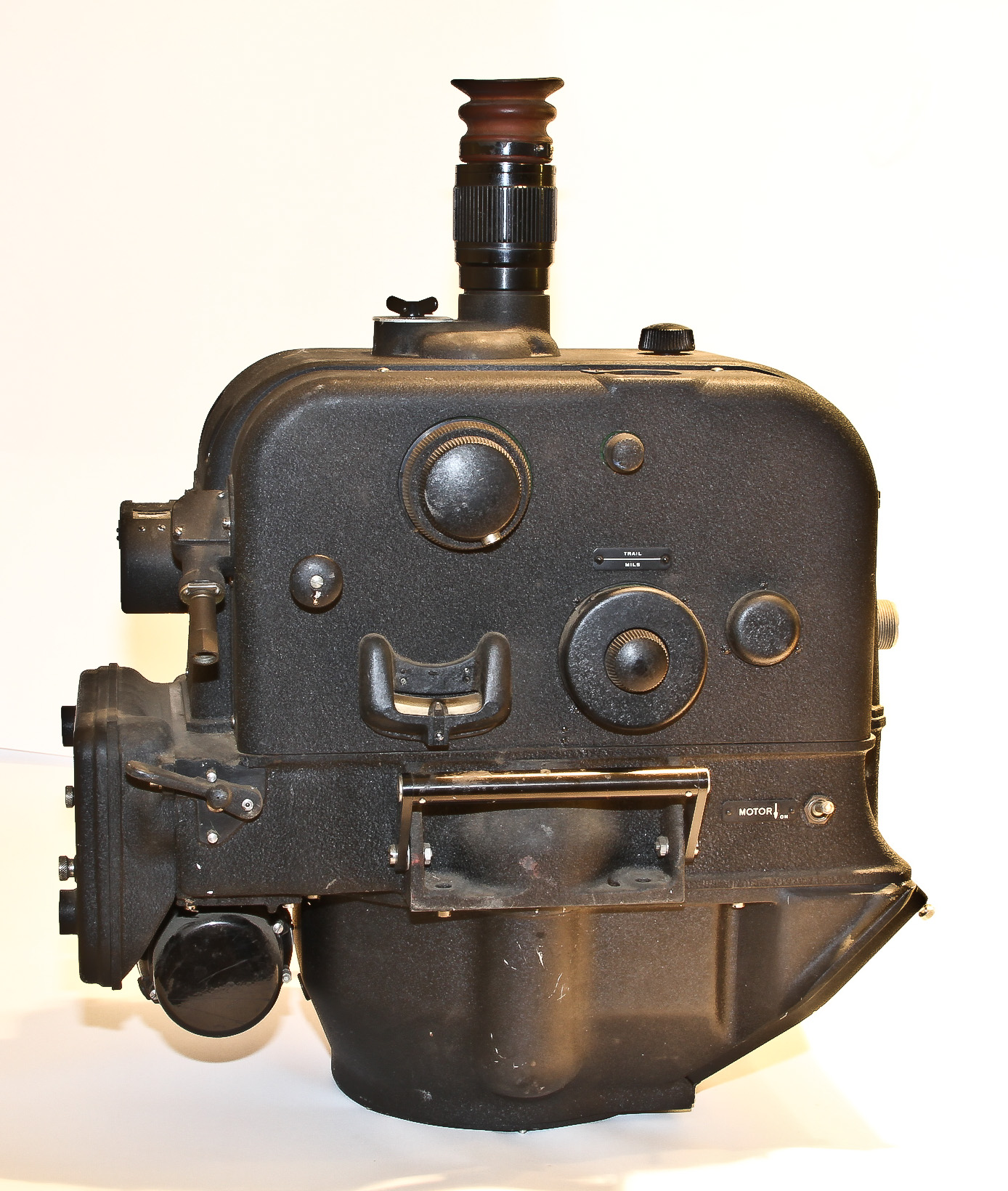
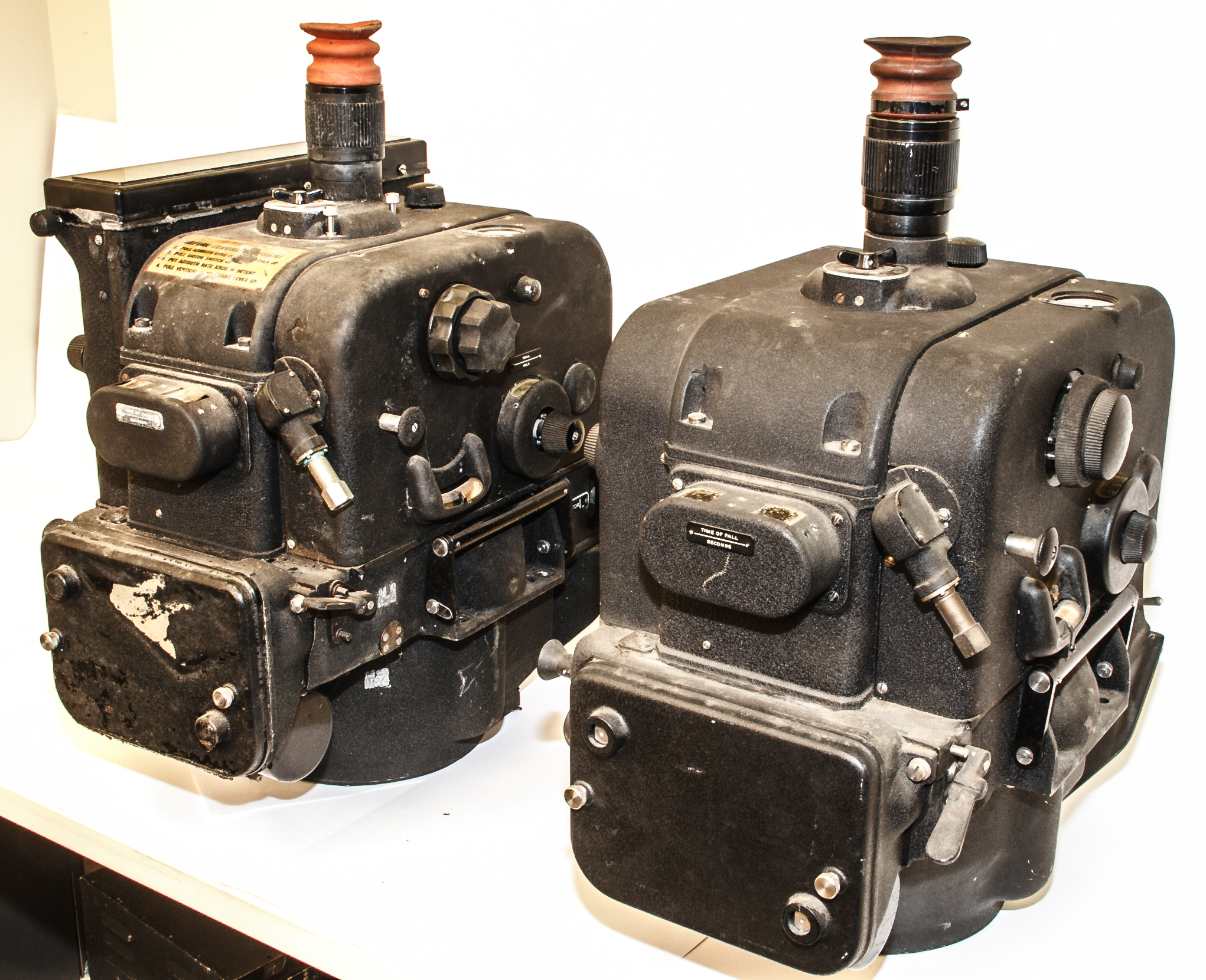
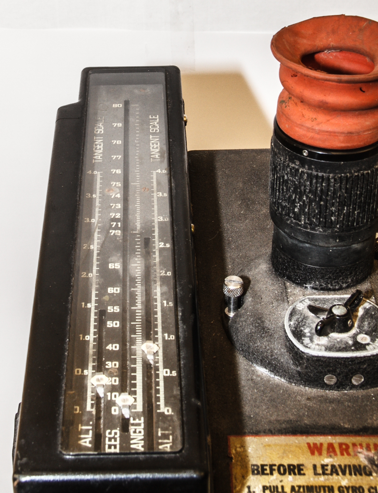
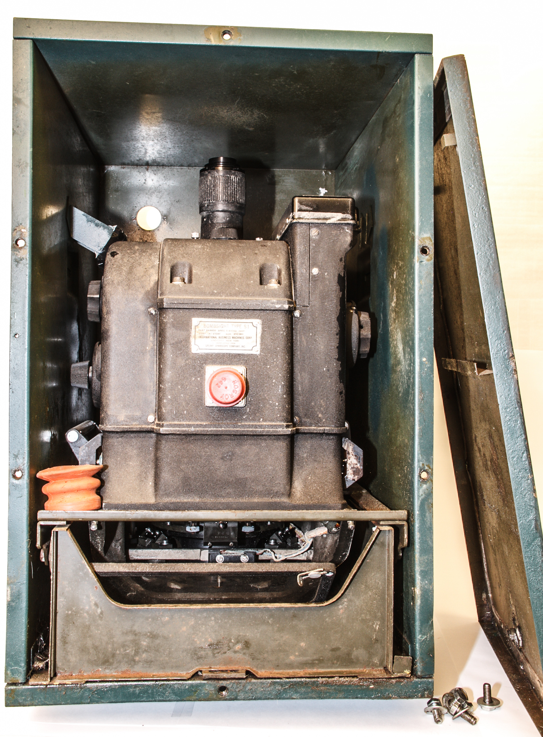
As shown in Figures 1 and 2, the Sperry S-l sight is essentially a cube with control (data input) knobs on each side and a vertically mounted telescopic viewing system. (Figure 2 shows the fact that we just acquired another S-1; see discussion of it below). The data input knobs are similar to the Norden bombsight, but were positioned on both sides of the instrument. Primary controls on the right side were concentric azimuth rate and displacement knobs, a cross-trail correction knob, a trail knob for setting in the standard value for the bomb, and a caging control for the vertical gyro. On the sight's left side were the concentric range displacement and rate knobs, a time-of-fall knob for setting in this bombing table datum, an angle sweep knob for initial location of target, and a caging control for the azimuth gyro. In Figure 1, the slanted portion at the bottom of the front is the viewing port of the telescope.
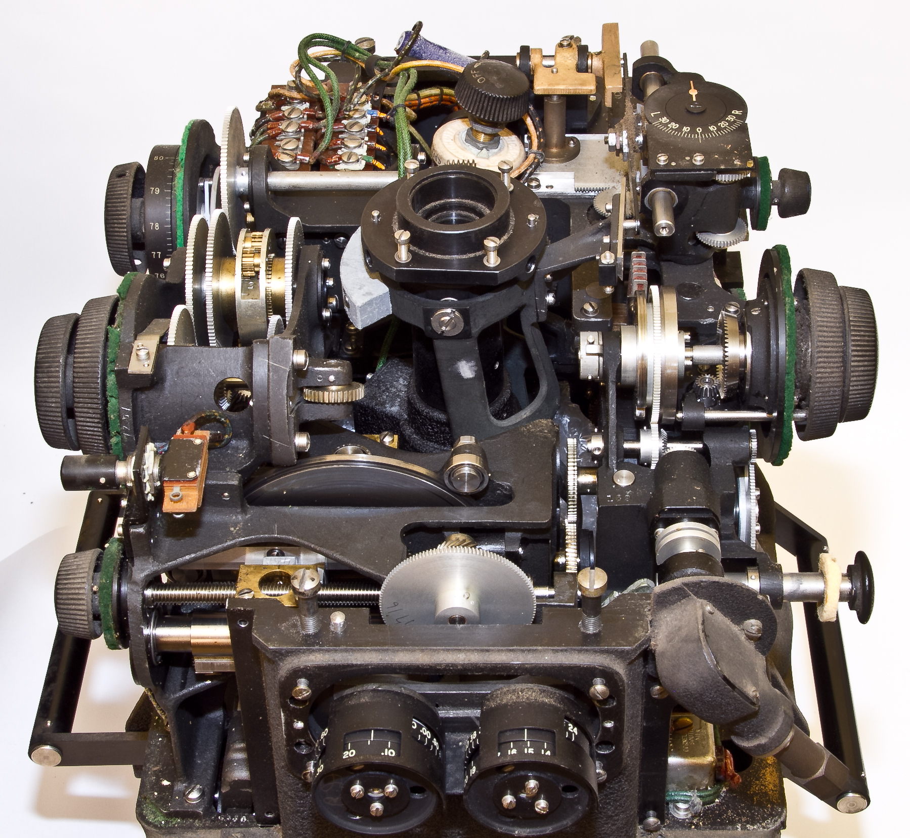
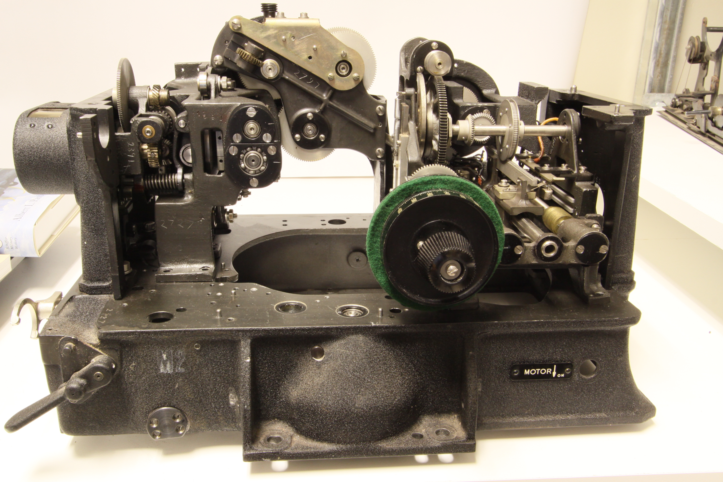
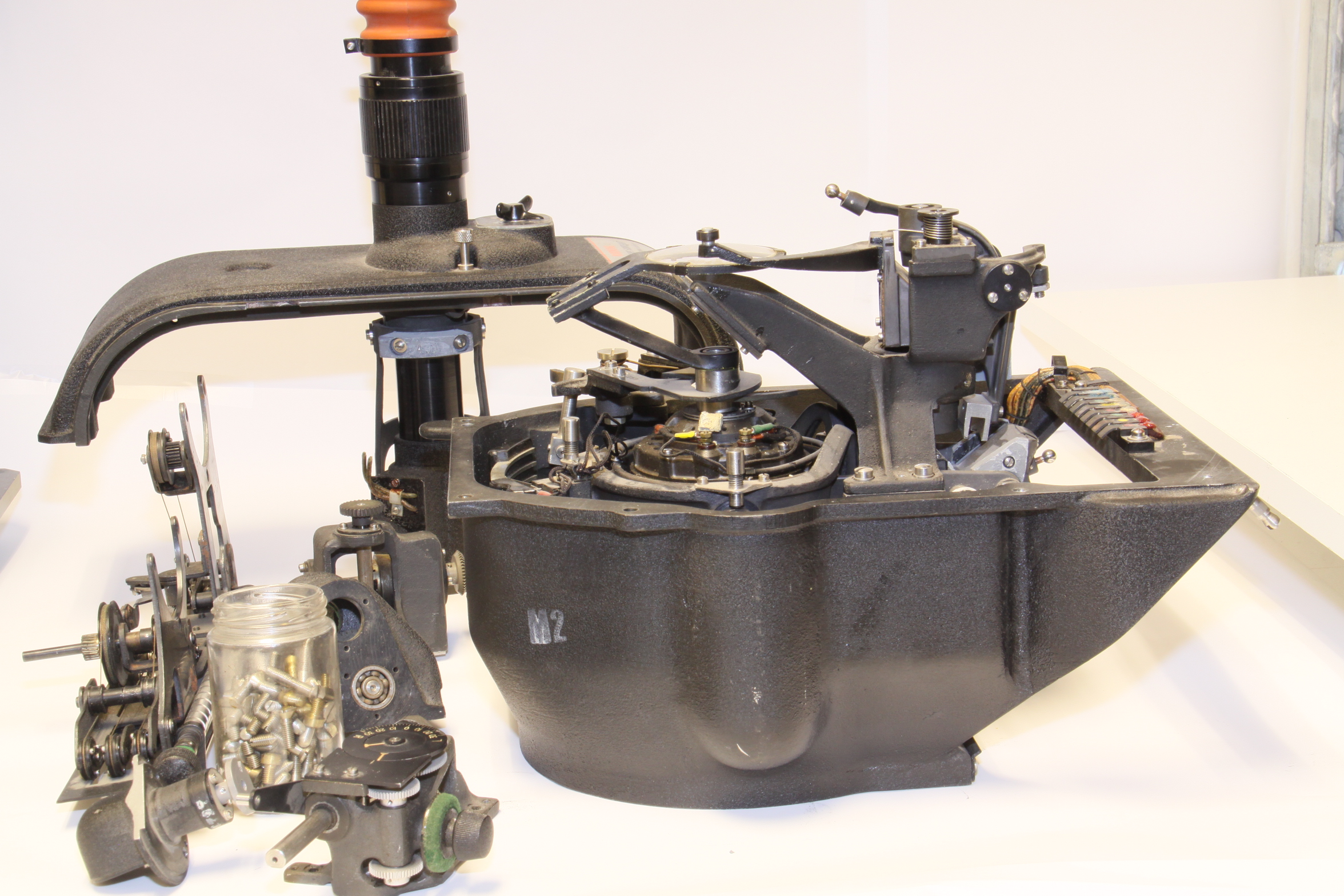
Figures 3,4 and 5 show some of the complicated mechanicals inside the S-1. It is hard to see, but Figure 5 shows the front of a disc integrator. The rotating disc in seen sticking up above the mechanism at the rear and the brass component is part of the mechanism that adjusts along the radius of the disc.
New news 3/2013: Even though I already have 1+ S-1 bombsights (see below), I just got another one which has some interesting and new (to my collection) features:
New news 10/2010: my original S-1 arrived in many pieces and I had long planned to reassemble it but reality has set in (reality = I never will get around to this) so I've now acquired a complete S-1.
Original news: I have acquired a disassembled S-1 as shown in Figures 11 and 12.
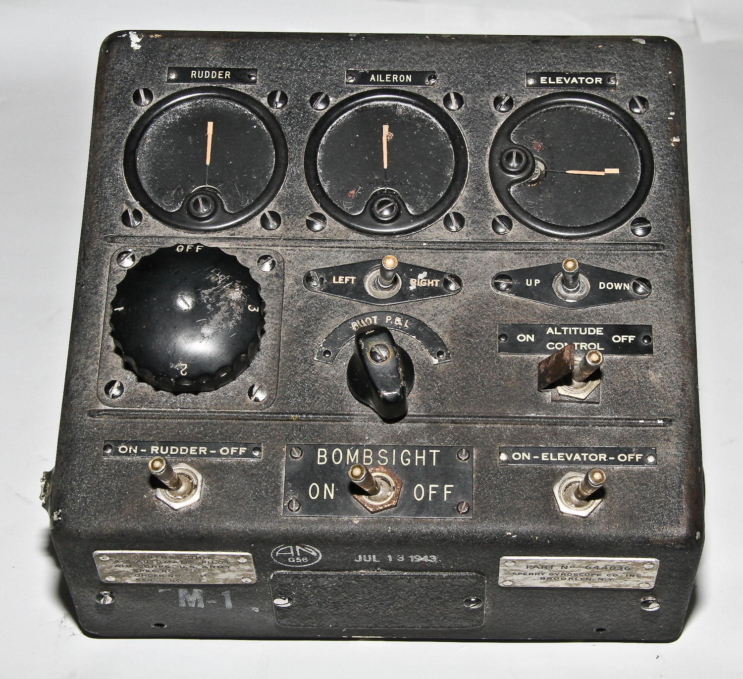
Also, Figure 13 shows the control panel for an A-5 autopilot which was developed to go with the S-1 bombsight. The A-5 seems to be the first all-electric three-axis autopilot (using tubes, of course).