Glenn’s Computer Museum |
| Home | New | Old Military | Later Military | Analog Stuff | IBM Stuff | S/3 Mod 6 | S/32 | Components | Encryption | Misc | B61 |
change log |
contact me |
![]()
Glenn’s Computer Museum |
| Home | New | Old Military | Later Military | Analog Stuff | IBM Stuff | S/3 Mod 6 | S/32 | Components | Encryption | Misc | B61 |
change log |
contact me |
![]()
World War II gave rise to some amazing electromechanical computers used by the military. The most impressive was the Navy's Mark I and Mark 1A fire control computers. used on battleships. A great reference to this device and many similar electromechanical fire control devices can be found at this site. Most of the complex fire control equipment, including the Mark I, was designed by the Ford Instrument Company (not associated with Ford Motors). Here is a great paper on Ford-designed mechanical analog computers.
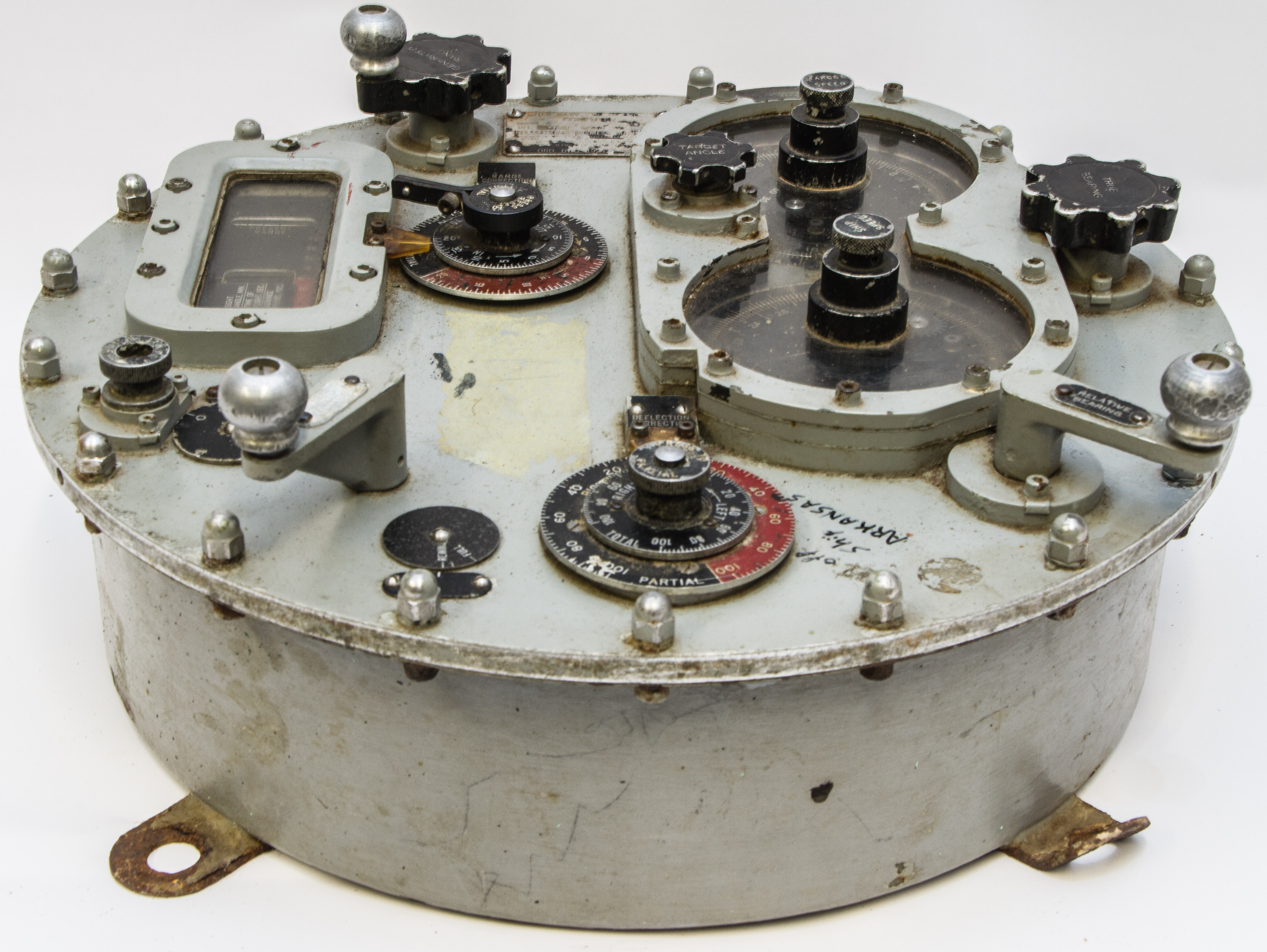
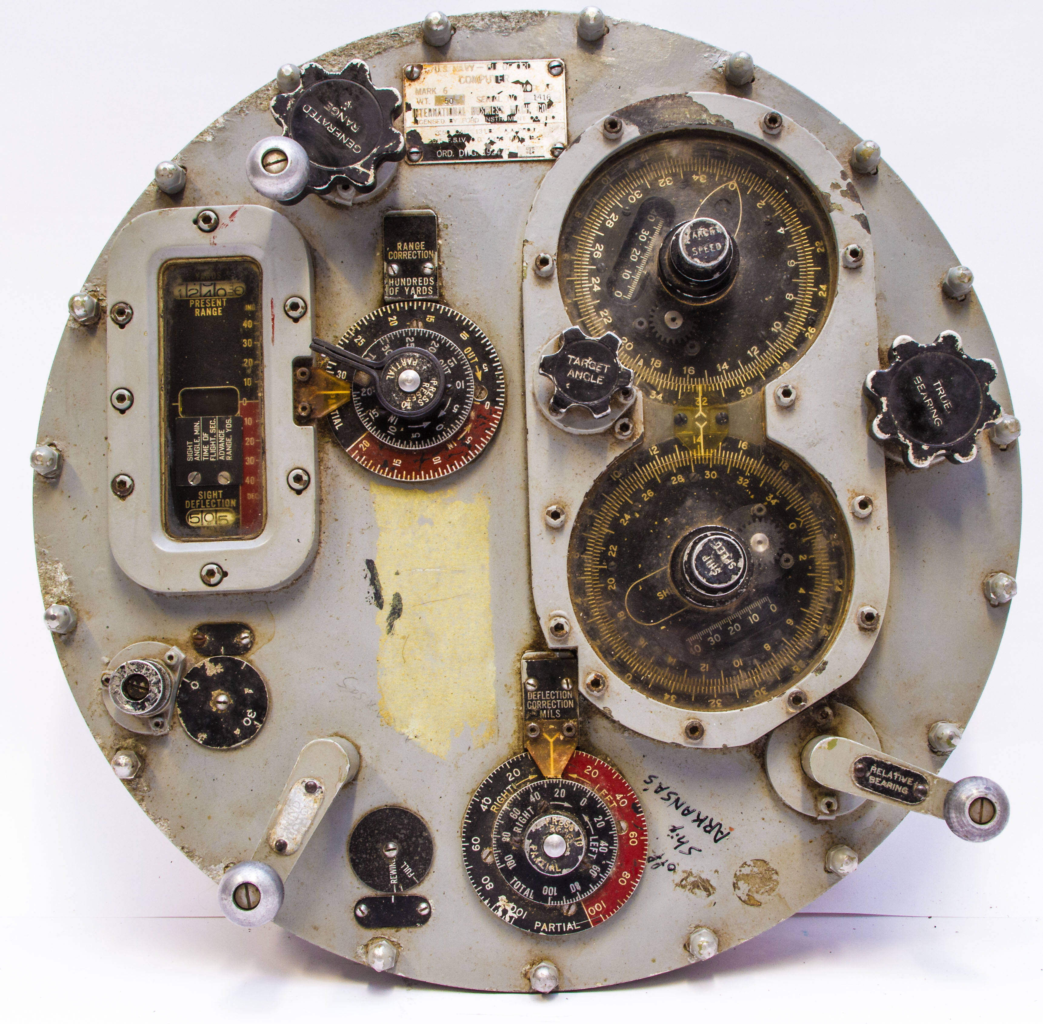
As far as I know, there are no intact versions of these large WWII devices outside of historic ships, although we have a couple of pieces of a Mark I in our museum. However, we do have a complete, but smaller, WWII fire control computer designed by the Ford Instrument company, and, interestingly, manufactured by IBM. It is mentioned in the above referenced paper, we find "Ford's answer to the merchant ship problem was the Computer Mark 6... Although only about the size of a large wheel of cheese, it ingeniously contained a simplified capability for solving the surface fire control problem."
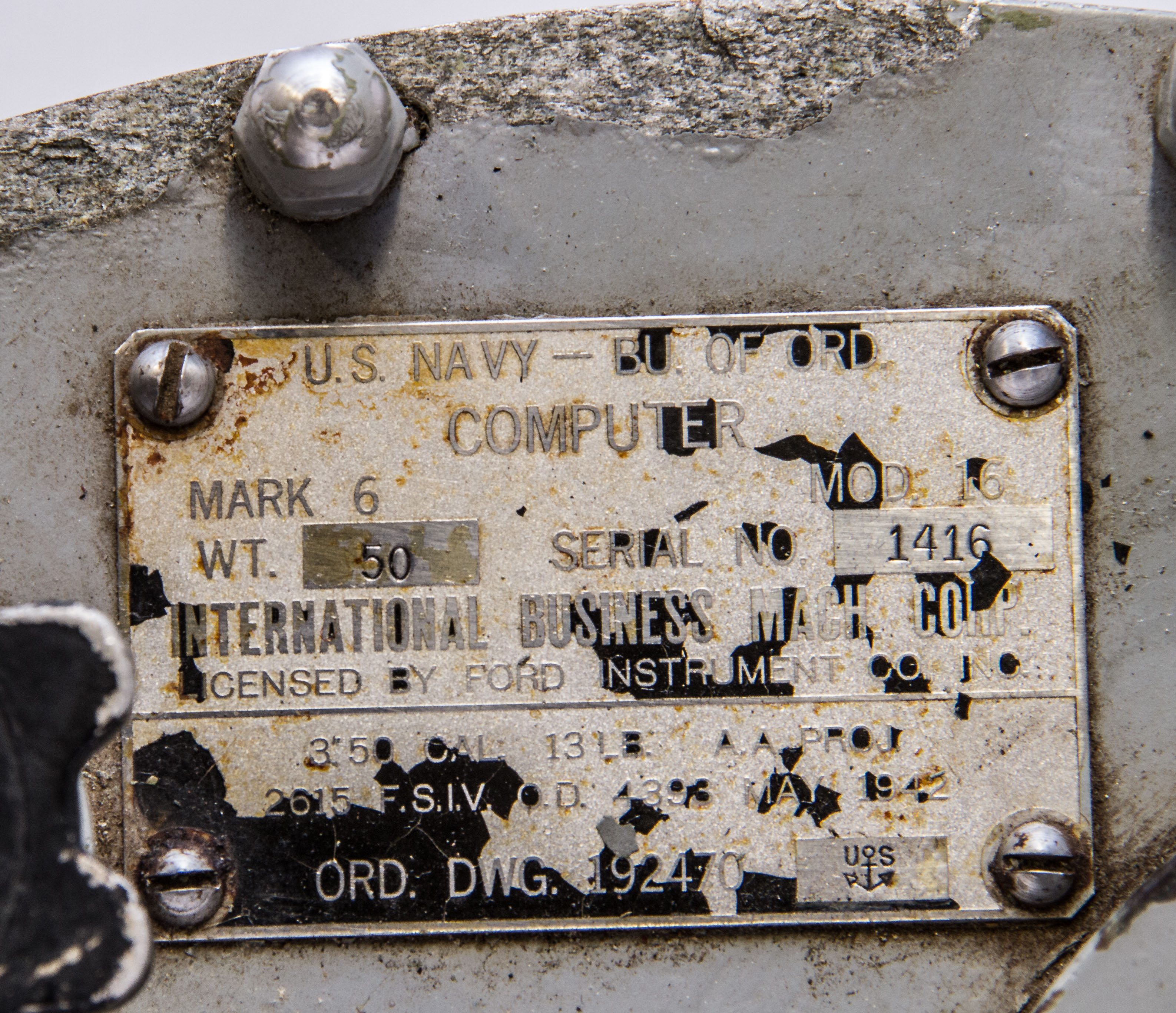
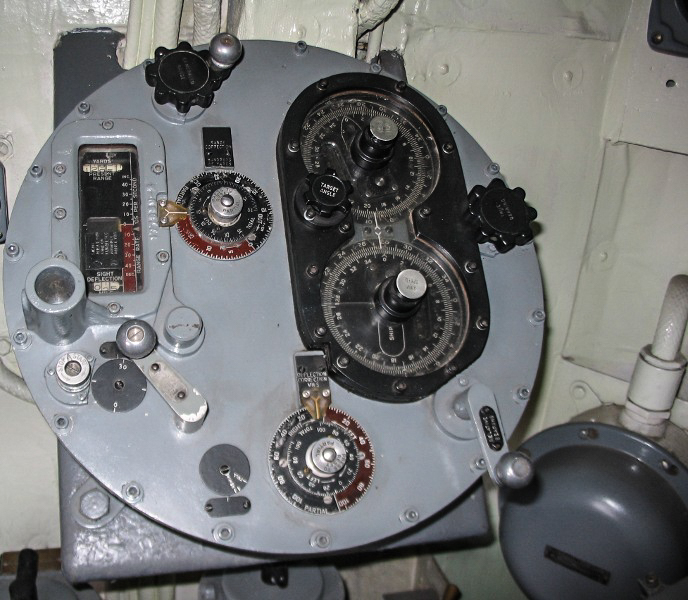
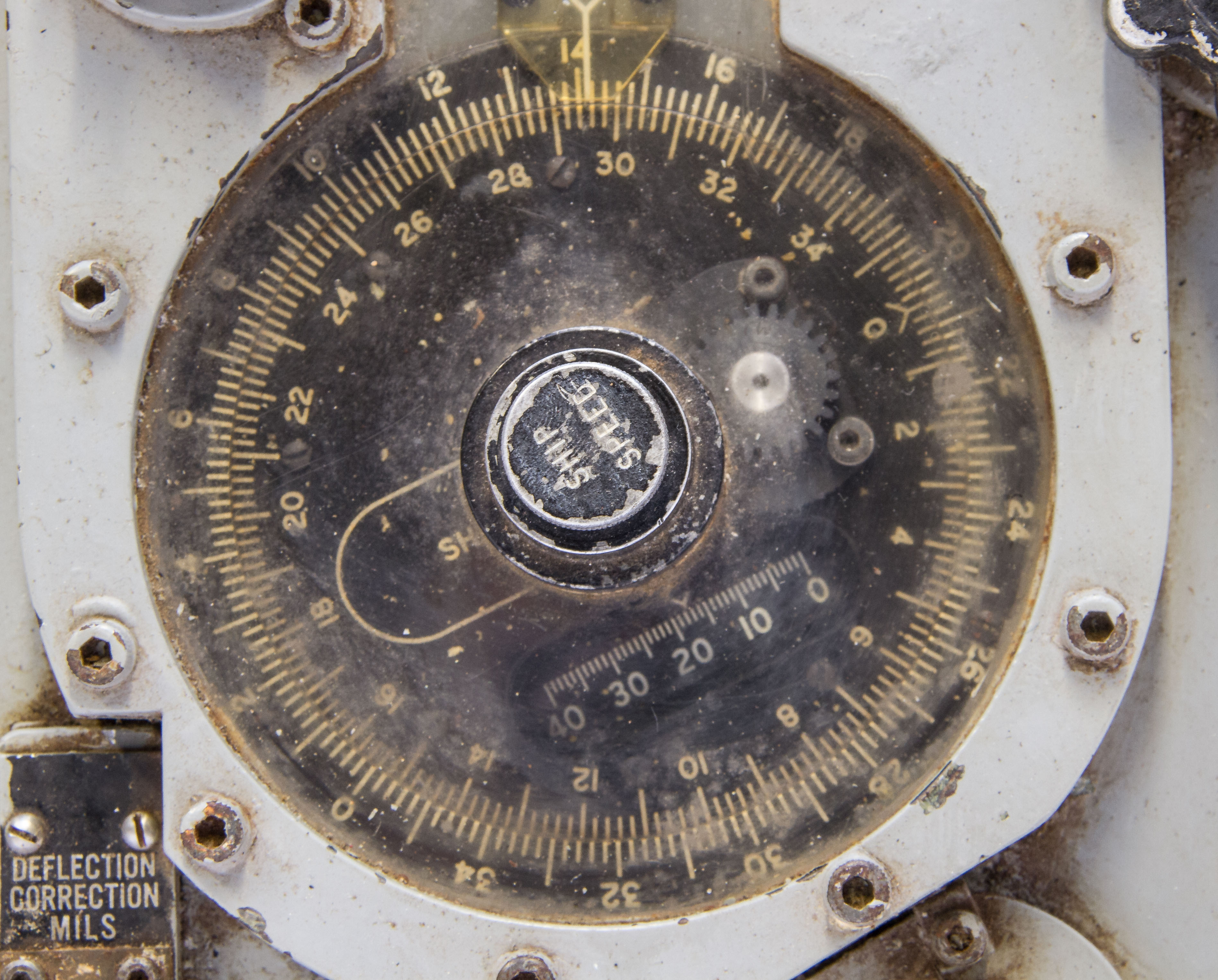
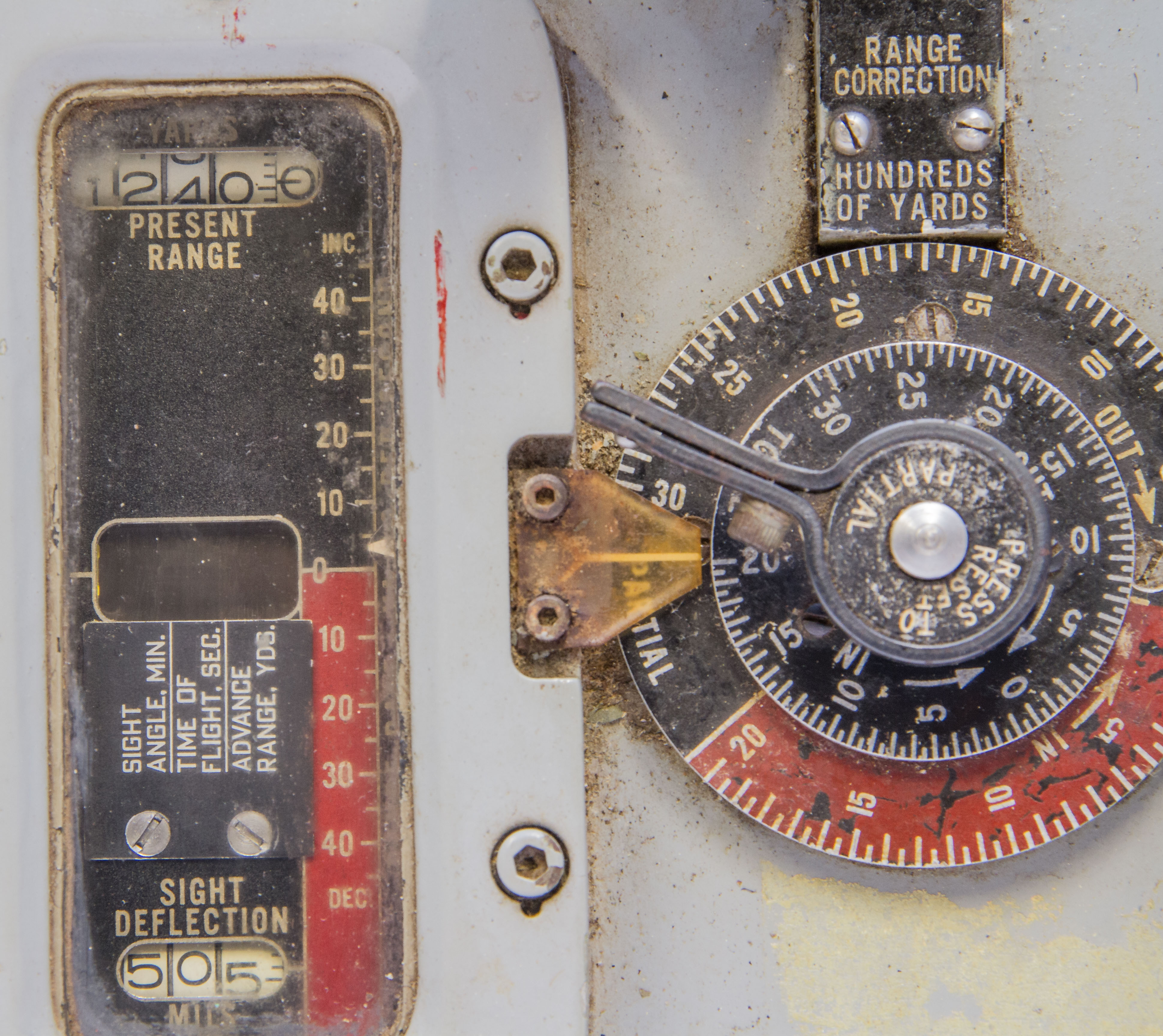
Figures 1 and 2 shows our "large wheel of cheese" sized Mark 6 mod 16 computer. Figure 3 shows a close up (hard to read, I recommend the largest size photo) of its label showing its pedigreed (Ford and IBM) along with a May 1942 date. The label notes that it is for a 3" 50-caliber gun shooting a 13 lb. AA projectile. Other WWII naval fire control computers were electrically powered; the Mark 6, however, is manually powered using a spring motor, wound by hand with the knob on the lower left of Figure 2.
I can find only three references to this device after significant searching: (1) the above mentioned paper on Ford computers, (2) Figure 9, a picture of the device in a restored WWII destroyer escort, and (3) Figure 16, a picture in a navy manual describing fire control equipment in a 16" gun turret.
(Both these sites are great if you are interested in navy ships, especially from WWII.)
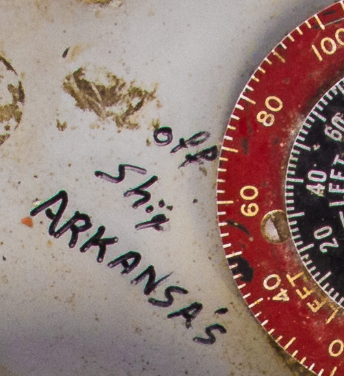
There are several mysteries here. First, even though the Ford computer reference above talks about defensively equipped merchant ships, Figure 6 shows that someone wrote "off ship Arkansa's" [sic] on our device. That seems to be a reference to an old WWII battleship, the USS Arkansas, BB-33, which, in fact, did have 3"/50 guns. In addition, we have the Figure 9 picture of our computer mounted in a destroyer escort. Since the 3"/50 gun was used on almost every US ship in WWII, it is likely that the Mark 6 computer was used on many ships. And, we have what must be a variant model associated with the main guns of a a battleship (Figure 9). The second mystery is the fact that the label mentions an "AA projectile", yet the details of the Mark 6 operation seem to be suited to ship-to-ship firing. Also, the above Ford reference talks about "surface fire control" for the Mark 6.
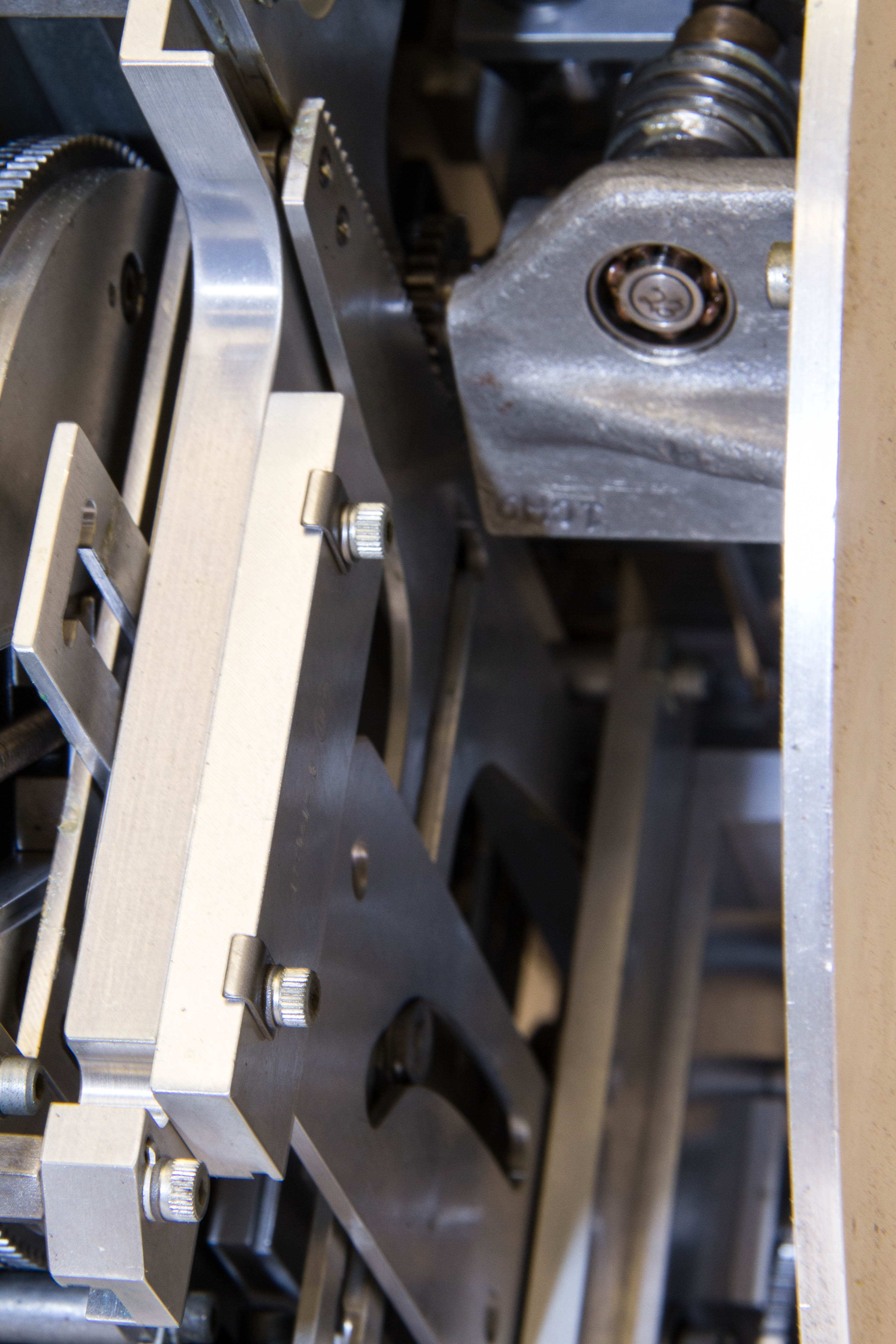
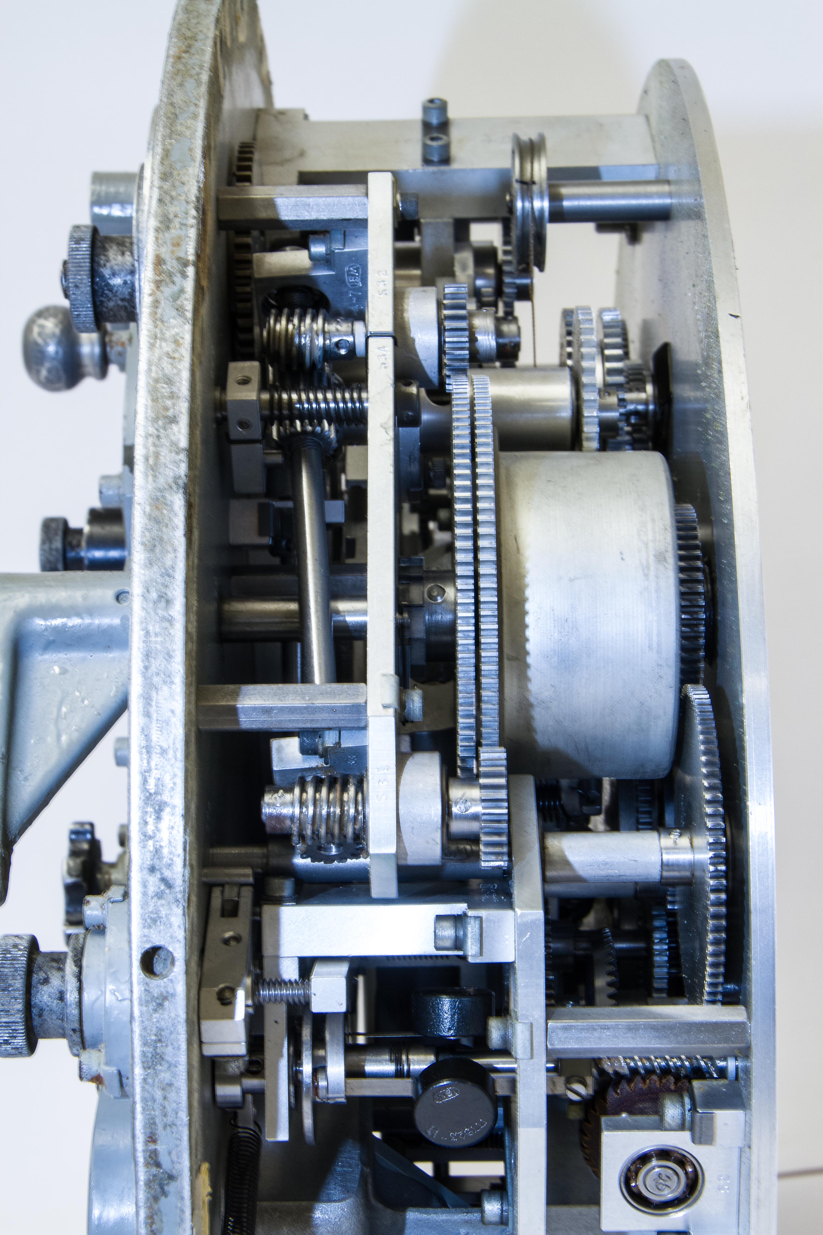
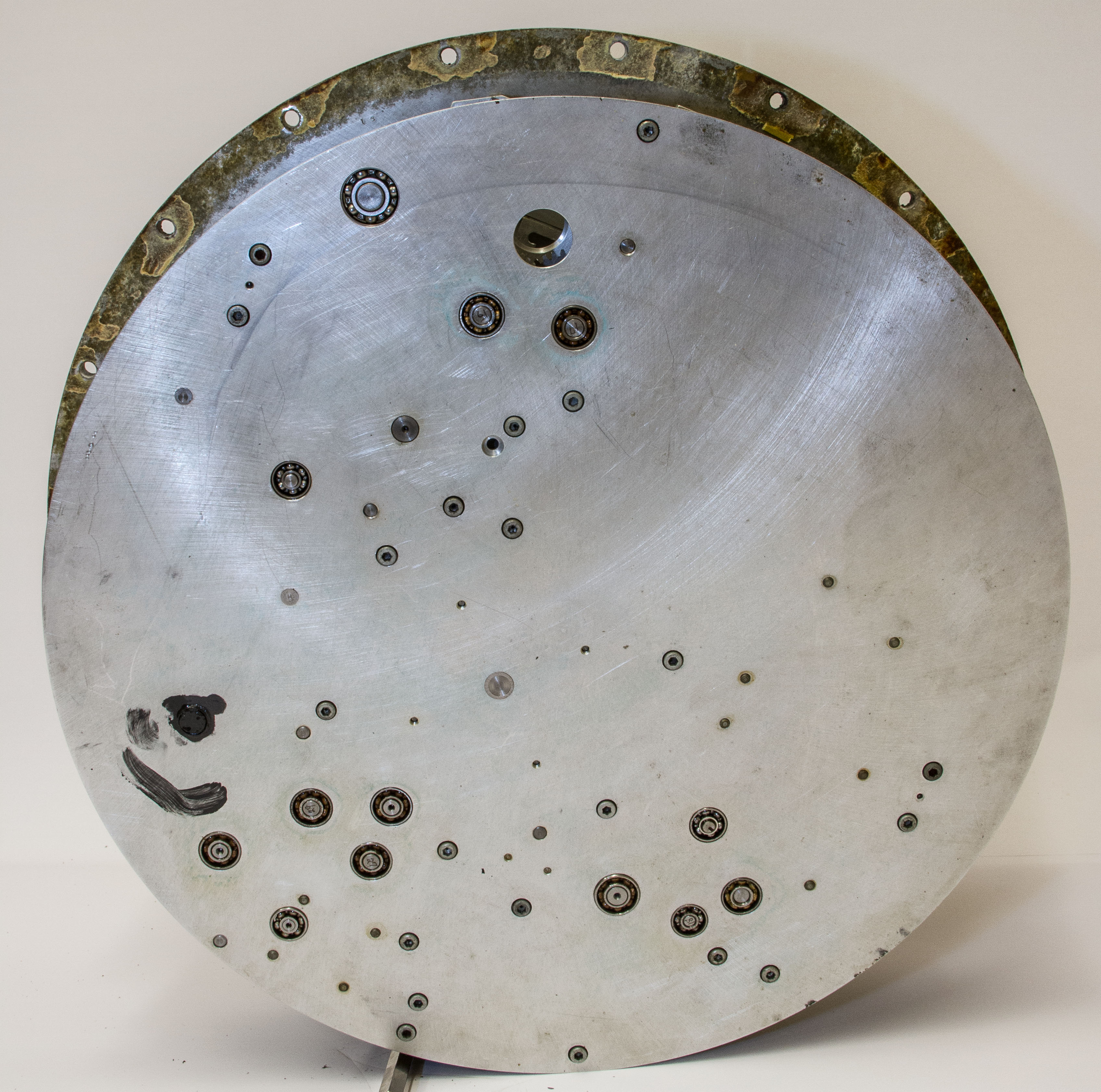
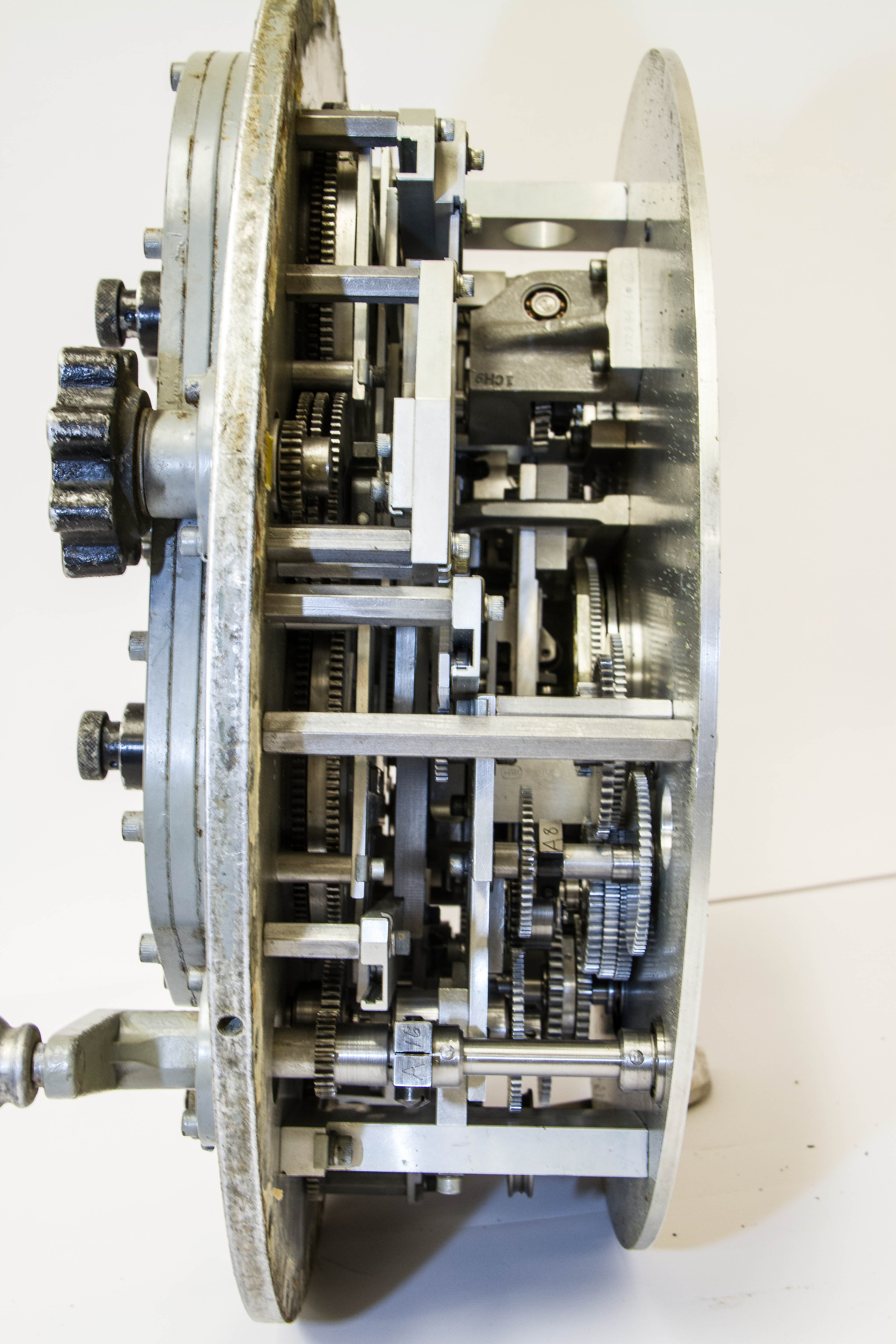
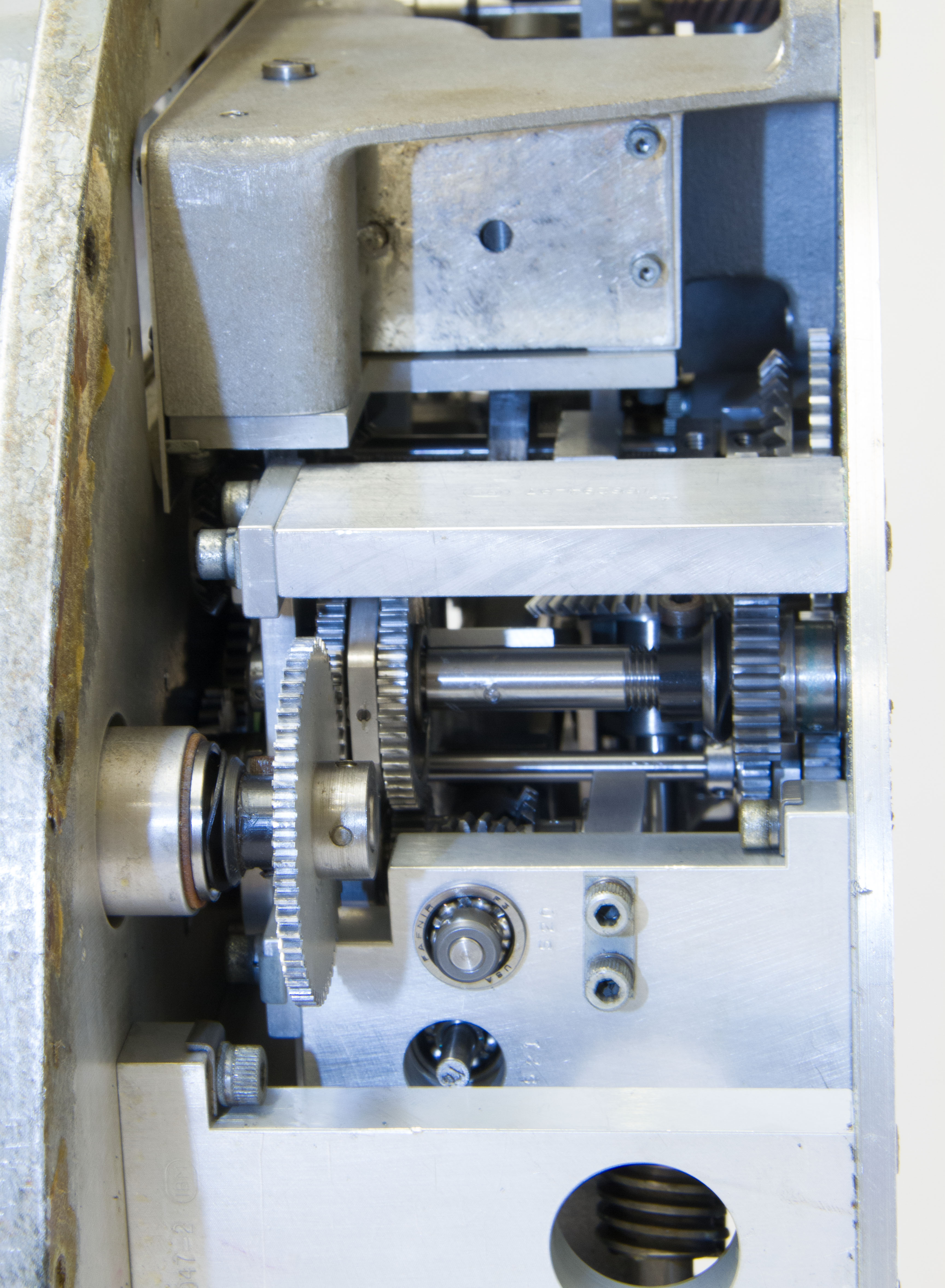
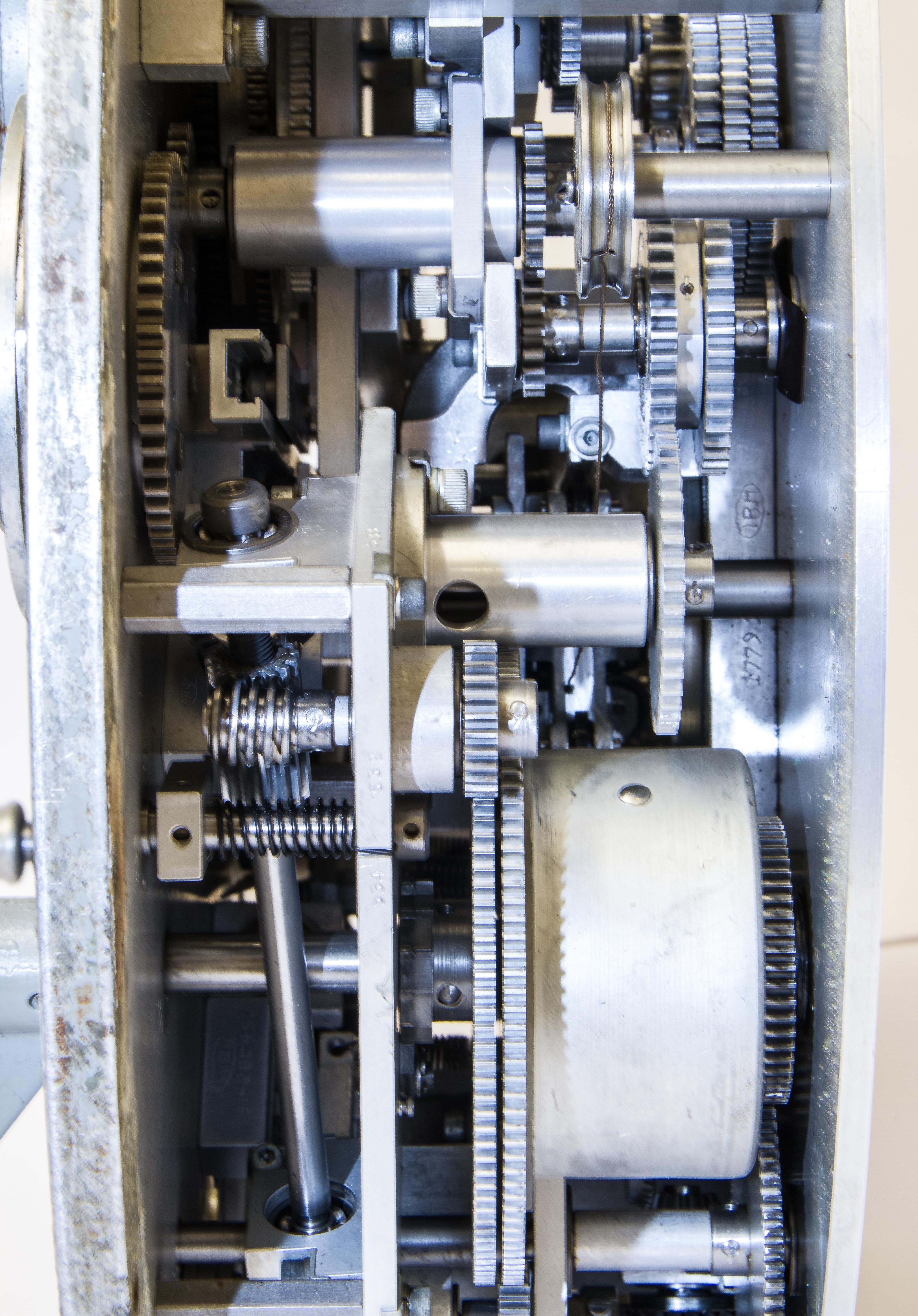
Finally after a lot of physical effort (the bolts were corroded), we have removed its case exposing its innards as shown in Figures 10-15. Figure 11 is a close-up of part of a mechanical multiplier that lies under the ship and target inputs. The spring that powers its calculations is a large cylinder shown in Figures 13 and 14. Near the bottom left of Figure 13 is the governor that tries to produce a constant speed output as the spring unwinds. Figure 15 is the back of the device showing the bearings for some of the mechanisms.
It is obvious from the dirt and marring on the face that this device was used. The insides, however, are pristine! And, the only lubrication is on the spring pedestal (the dark blob on the bottom left of Figure 15).