Glenn’s Computer Museum |
| Home | New | Old Military | Later Military | Analog Stuff | IBM Stuff | S/3 Mod 6 | S/32 | Components | Encryption | Misc | B61 |
change log |
contact me |
![]()
Glenn’s Computer Museum |
| Home | New | Old Military | Later Military | Analog Stuff | IBM Stuff | S/3 Mod 6 | S/32 | Components | Encryption | Misc | B61 |
change log |
contact me |
![]()
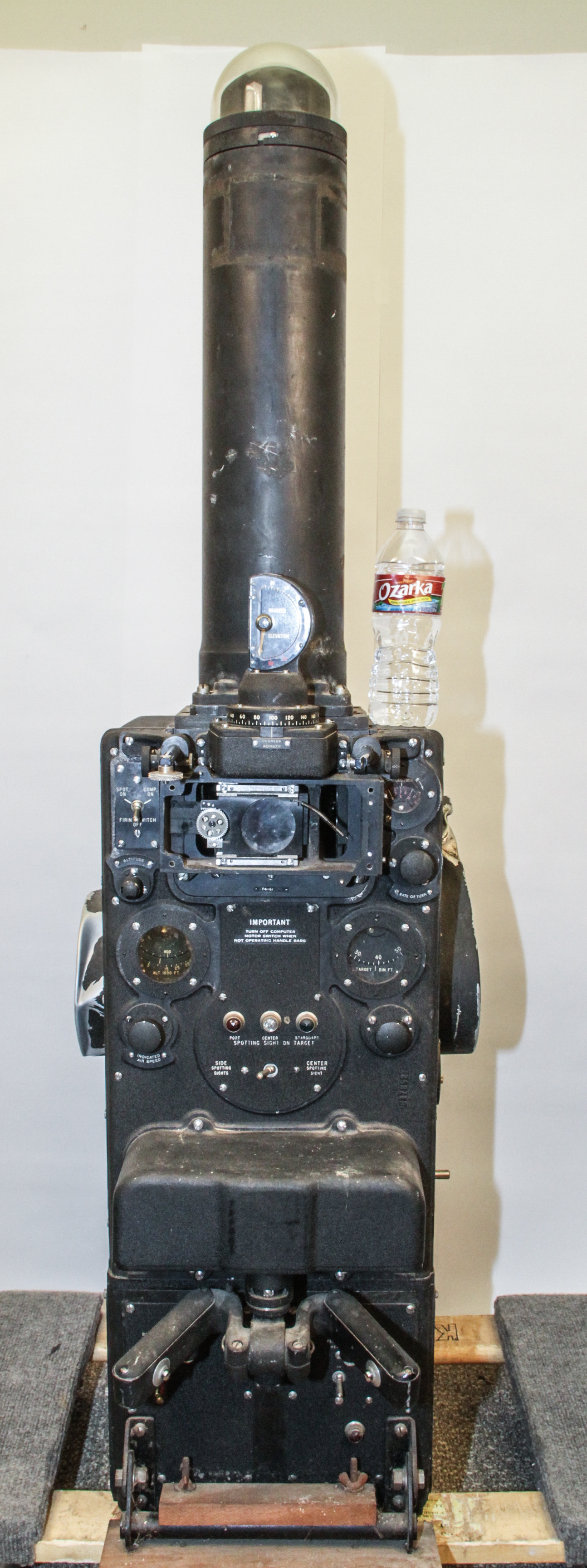
Here is a extremely rare device, an electromechanical Sperry P-4 (Gunsight) Computer. The only good information I could find about this device can be found in this very interesting article describing another museum's (a real one) P4.
Briefly, the background is that the P-4 was originally designed as part of a central fire control system for the remote control of bomber gun turrets primarily for the B-29 and B-32 bombers (the B-32 was a backup in case of problems with the B-29 program). Ultimately, the Sperry P-4 was not chosen by the Army and was replaced by the GE-designed fire control system covered elsewhere in the museum. According to the referenced article, only 460 P-4 systems were contracted for and the number actually built out of these 460 is unknown as the contract was canceled before they were all built. There were several factors that lead to the GE system being chosen, including P-4 schedule delays, but one of the most critical was the small field of view from the periscope.
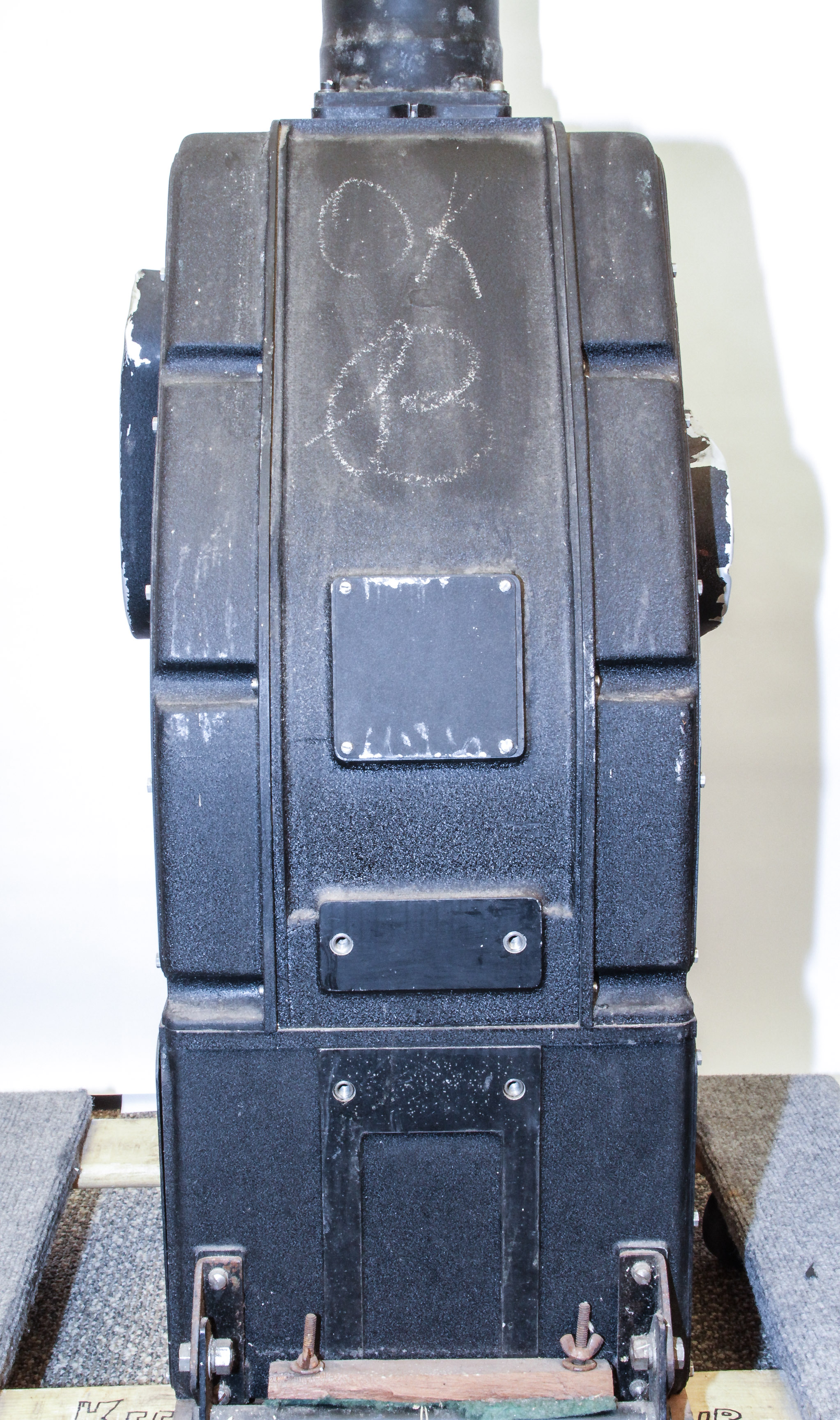
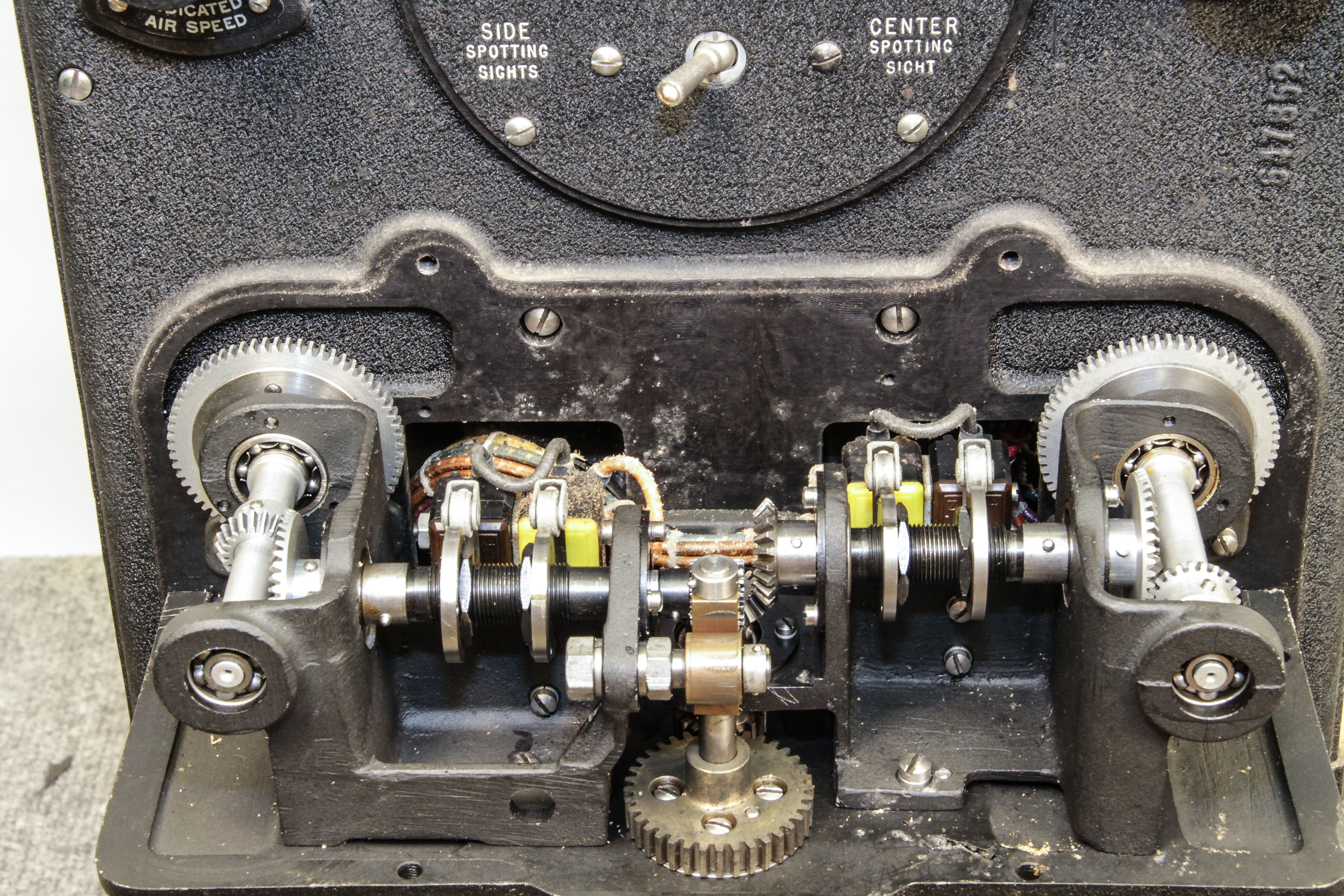
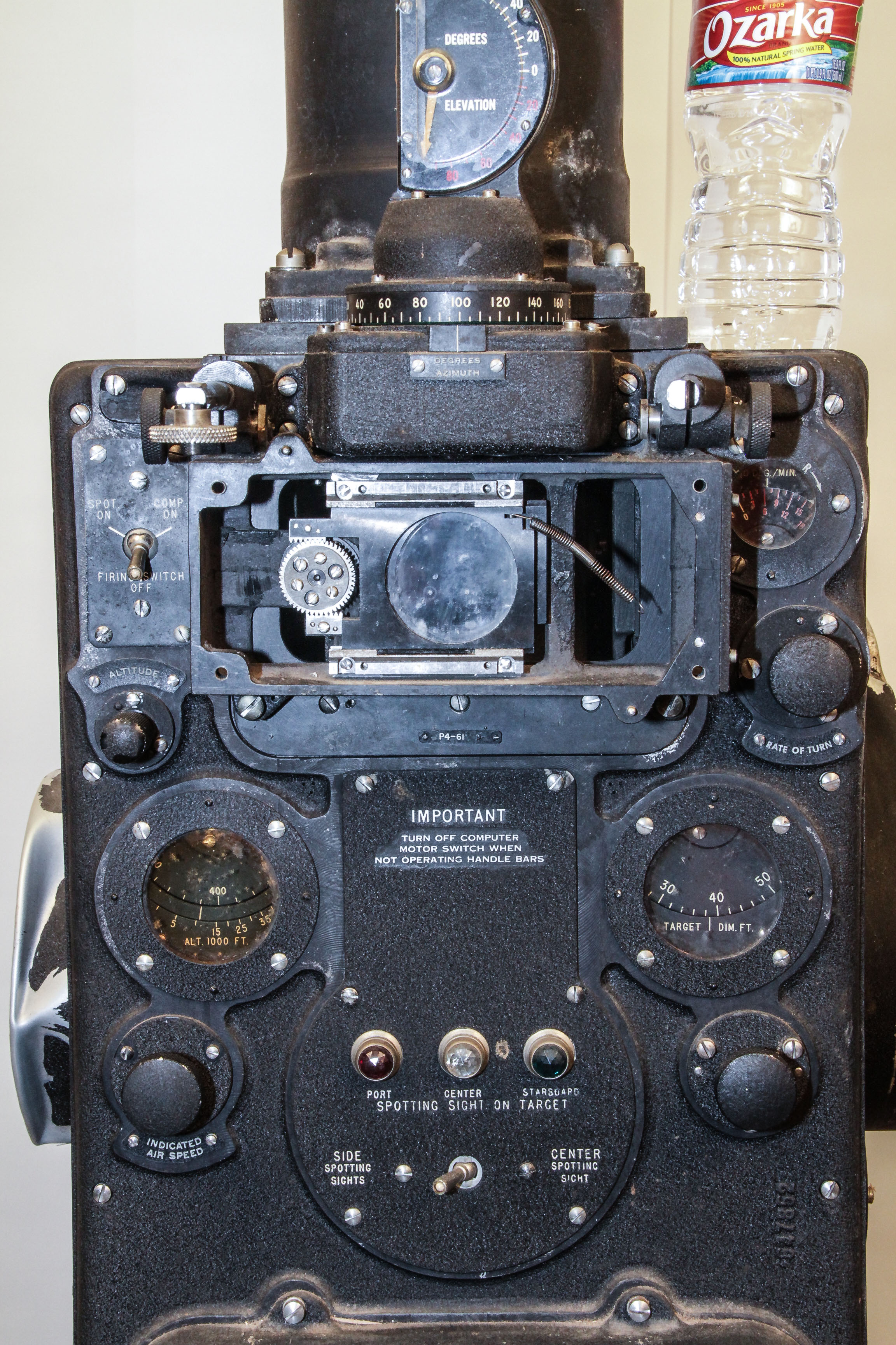
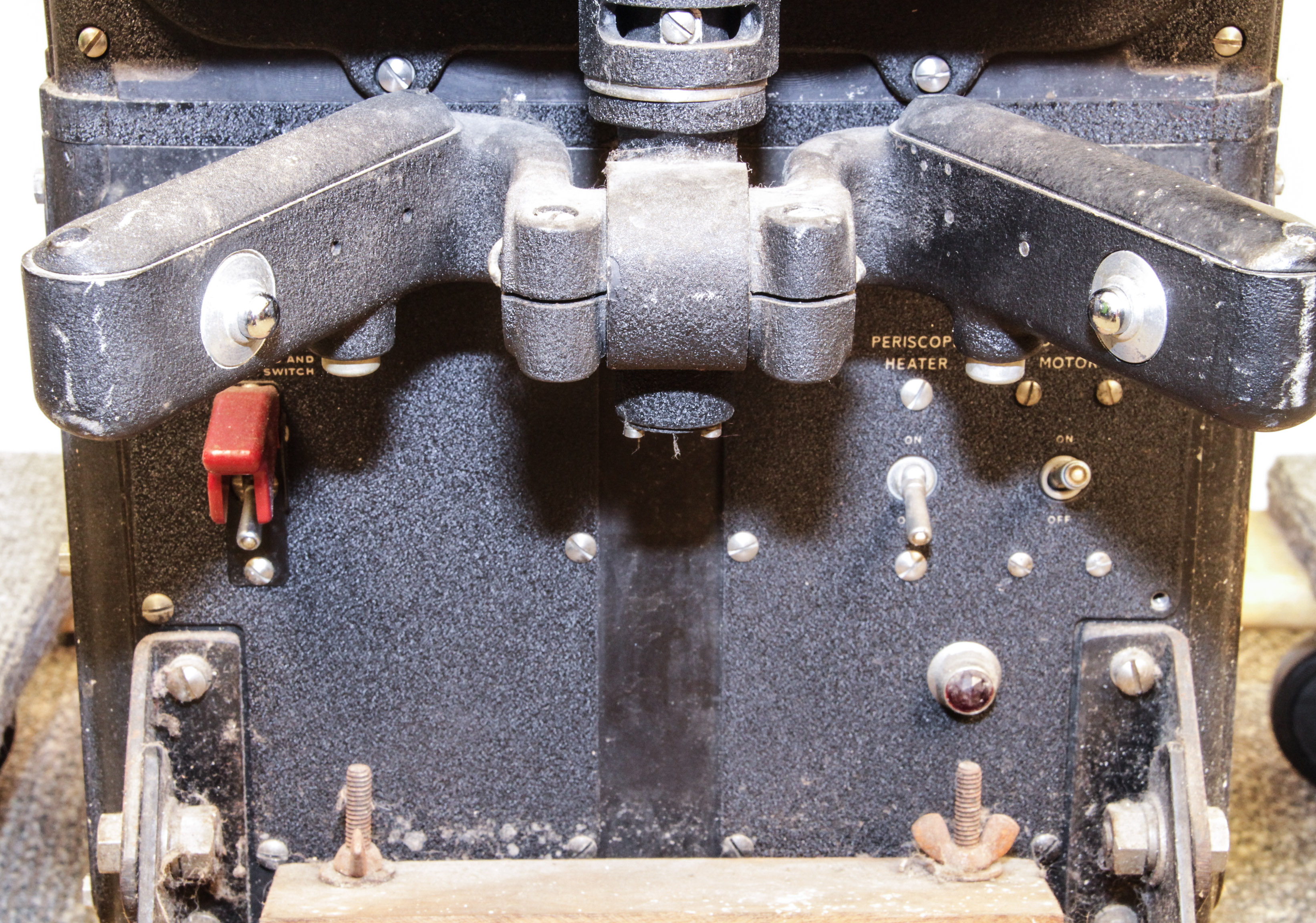
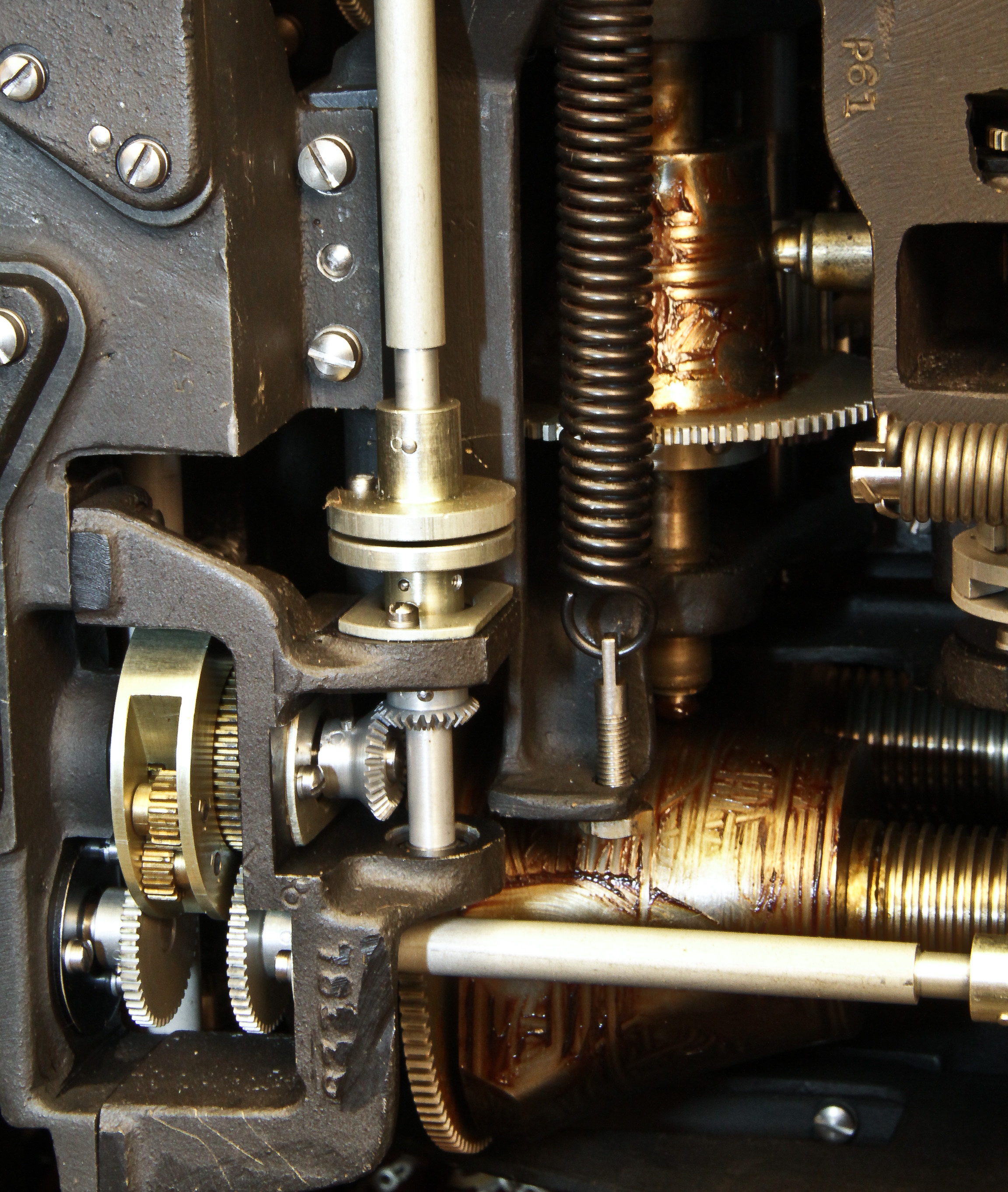
Our P-4 is about six-feet tall and weights about 200 pounds!. Figure 1 shows the front of the entire device (a water bottle show the scale). The periscope on the top looked out through a window on the top of the centrally located sighting compartment on the plane. Just below the base of the periscope, Figure 2 shows the eyepiece for viewing (our device is missing part of the the eyepiece), and the controls and readouts for items like airspeed and altitude. Below that, shown in Figure 6, are the steering controls for manipulating the left-right and up-down of the view through the periscope. Figure 7 show the mechanism to translate the control movements. Figure 3 show the back of the device, slanted (as can be seen in Figures 4 and 5) to fit (I guess) the upper curve of the fuselage. There was also a foot pedal connected to a rod on the side for zooming the view. Our device is missing this foot pedal. It also has damaged side panels. Otherwise, the insides seem pristine: in Figure 8 notice the grease on the three-dimensional cams.
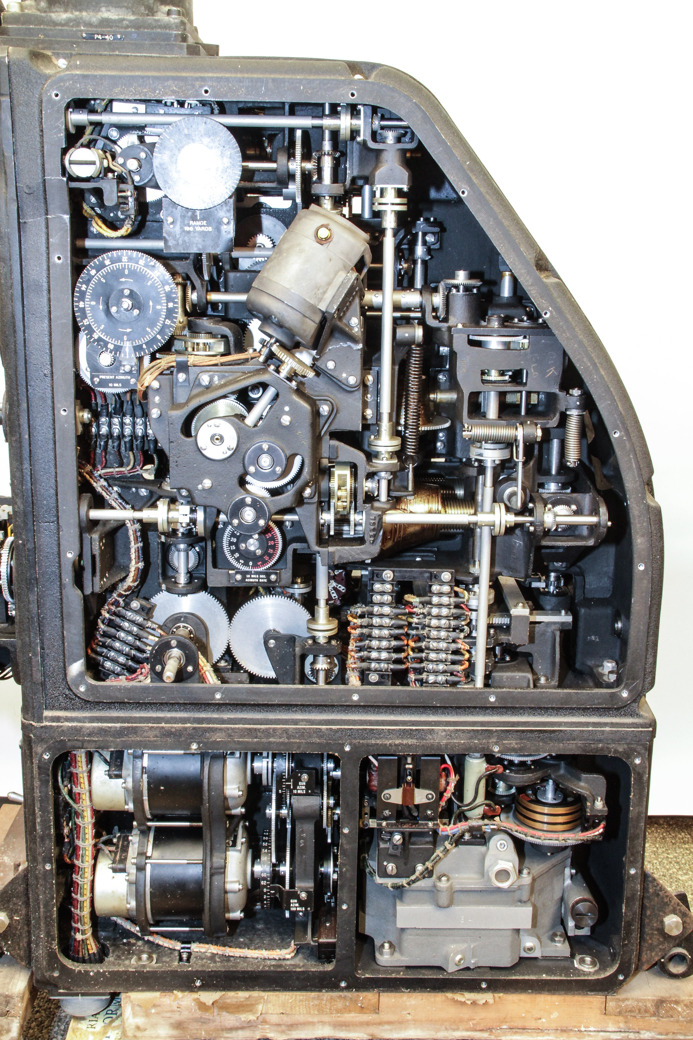
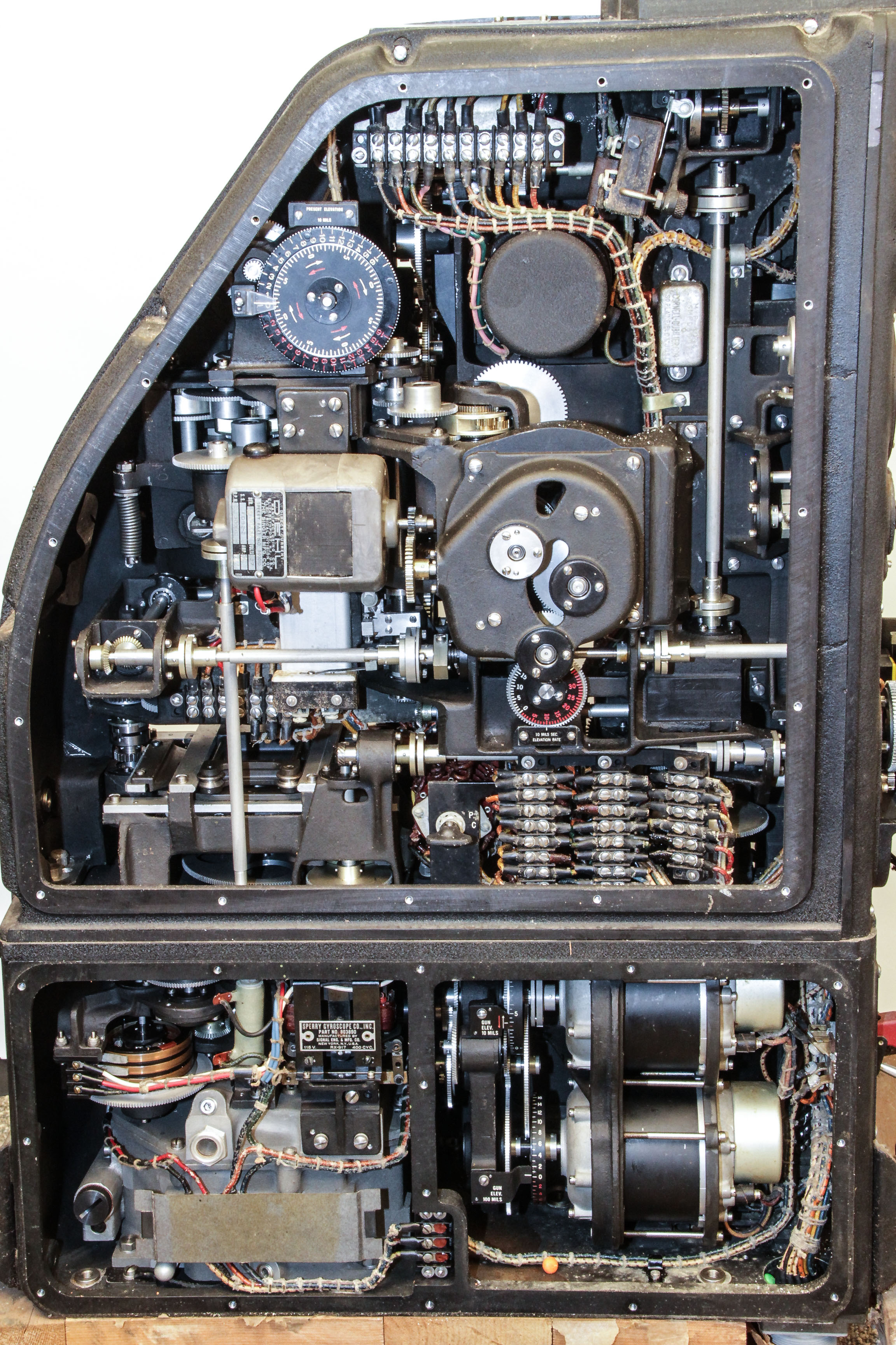
The real interest is the internal computing mechanisms show in the side views of Figures 4 and 5 (obviously the side panels have been removed.). In person, the details are very impressive. Much of the mechanical computing elements are not easily seen in these pictures. Figure 8 is just one example of the complexity that lies deeper within the case.
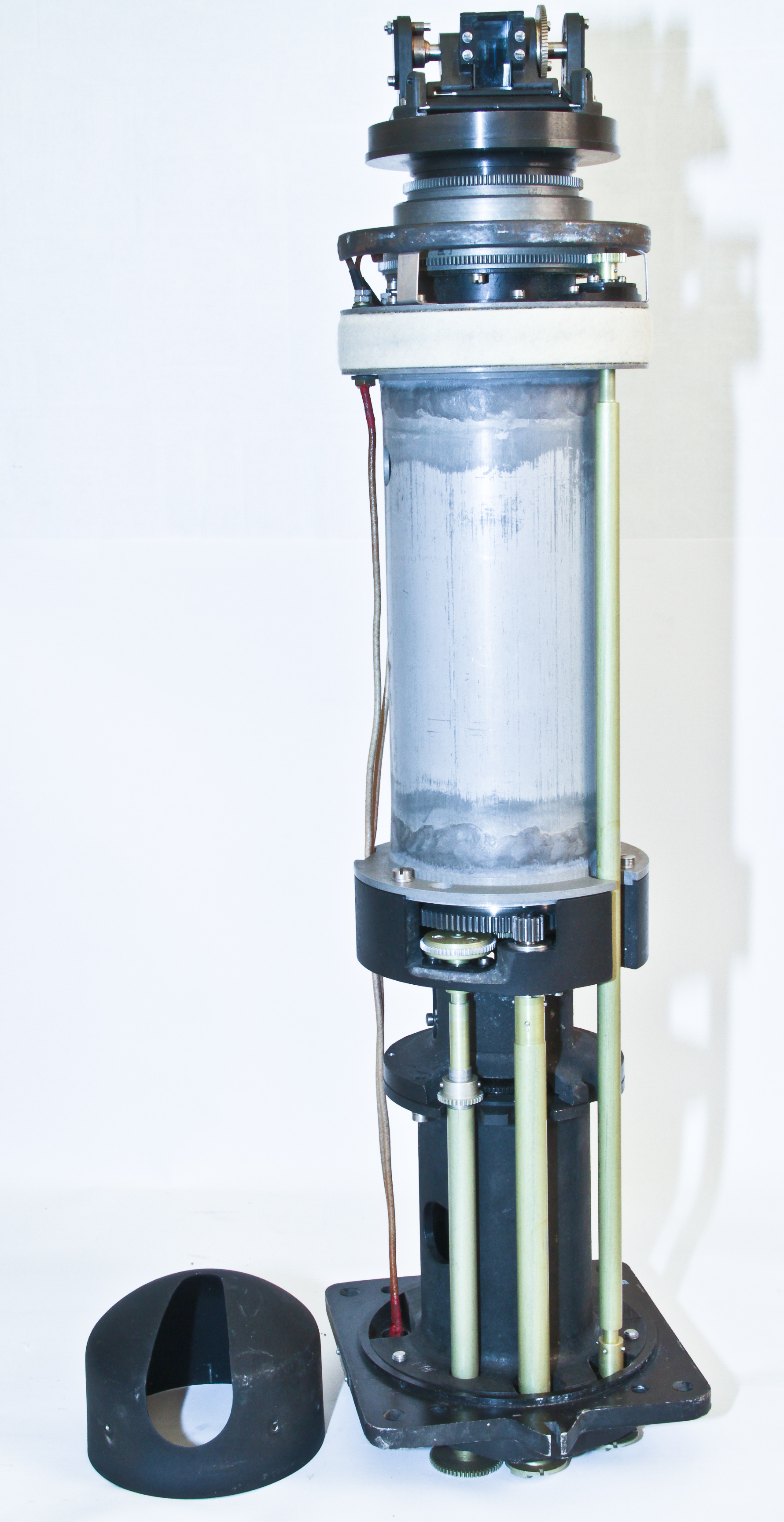
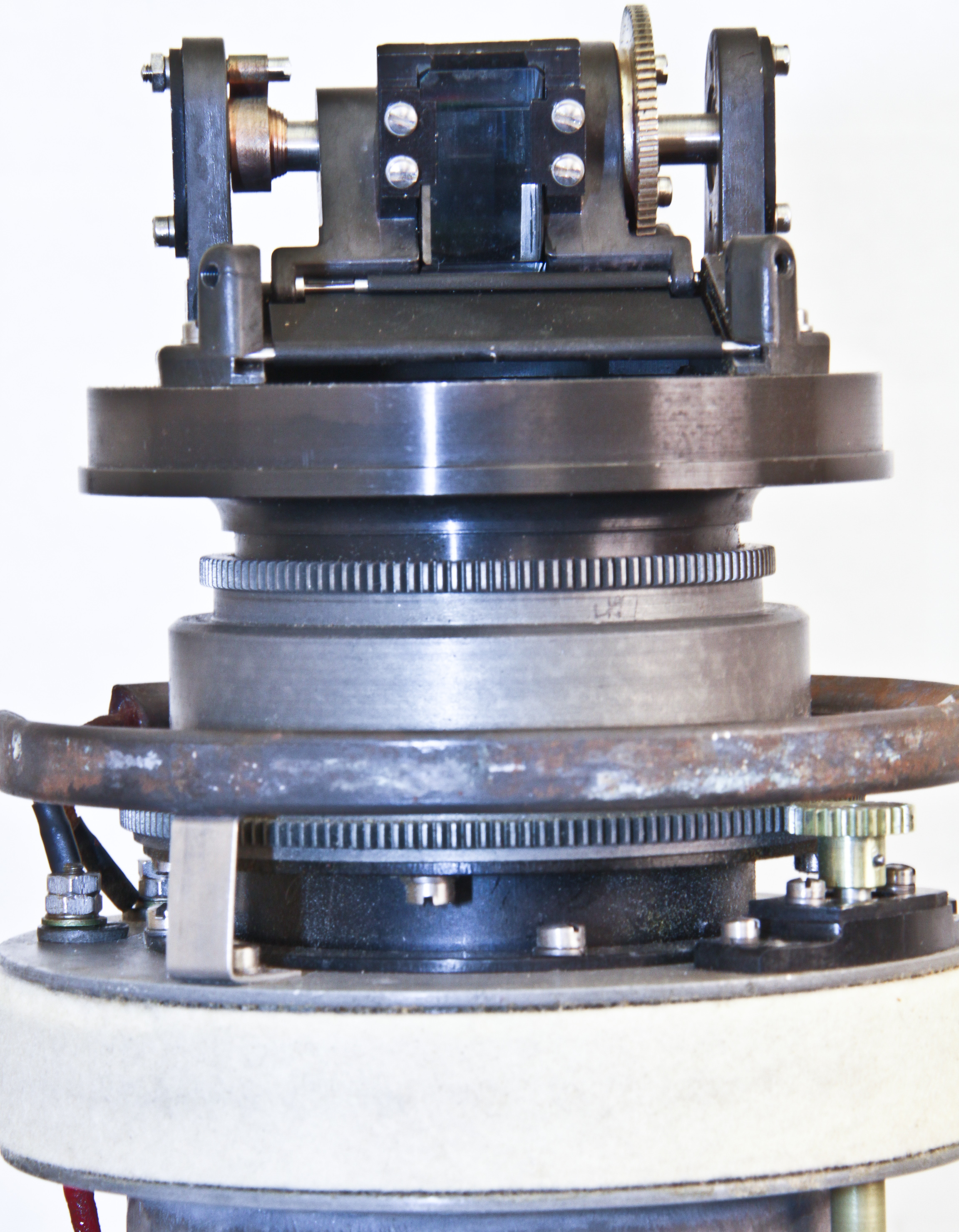
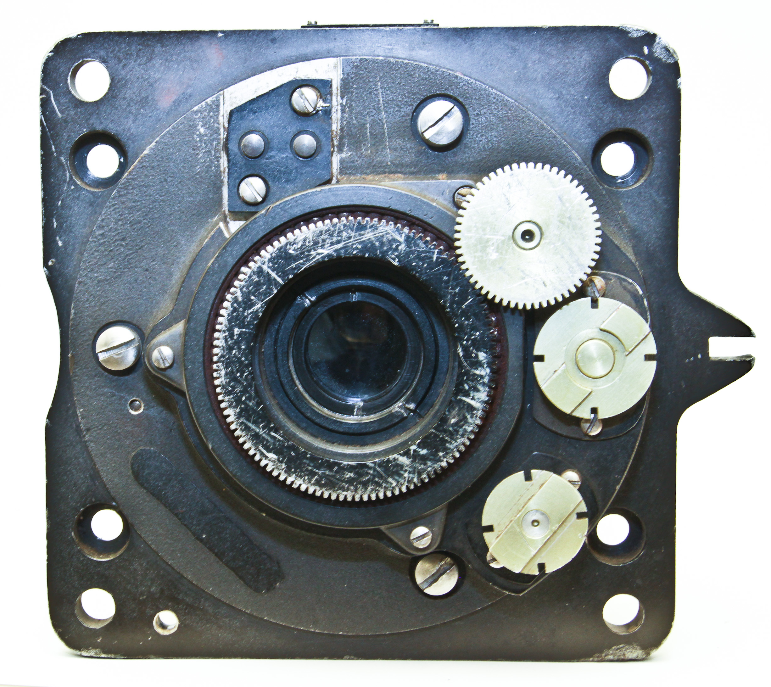
Figures 10,11, and 12 show the periscope with its case removed. There are three controls attaching to the computer unit: pan, tilt, and zoom. These controls is transferred from three rods that attach to matings at the bottom of the periscope. There is also a heating element. Note the very small optical element (a prism); it is about the size of a thumbnail.