Glenn’s Computer Museum |
| Home | New | Old Military | Later Military | Analog Stuff | IBM Stuff | S/3 Mod 6 | S/32 | Components | Encryption | Misc | B61 |
change log |
contact me |
![]()
Glenn’s Computer Museum |
| Home | New | Old Military | Later Military | Analog Stuff | IBM Stuff | S/3 Mod 6 | S/32 | Components | Encryption | Misc | B61 |
change log |
contact me |
![]()


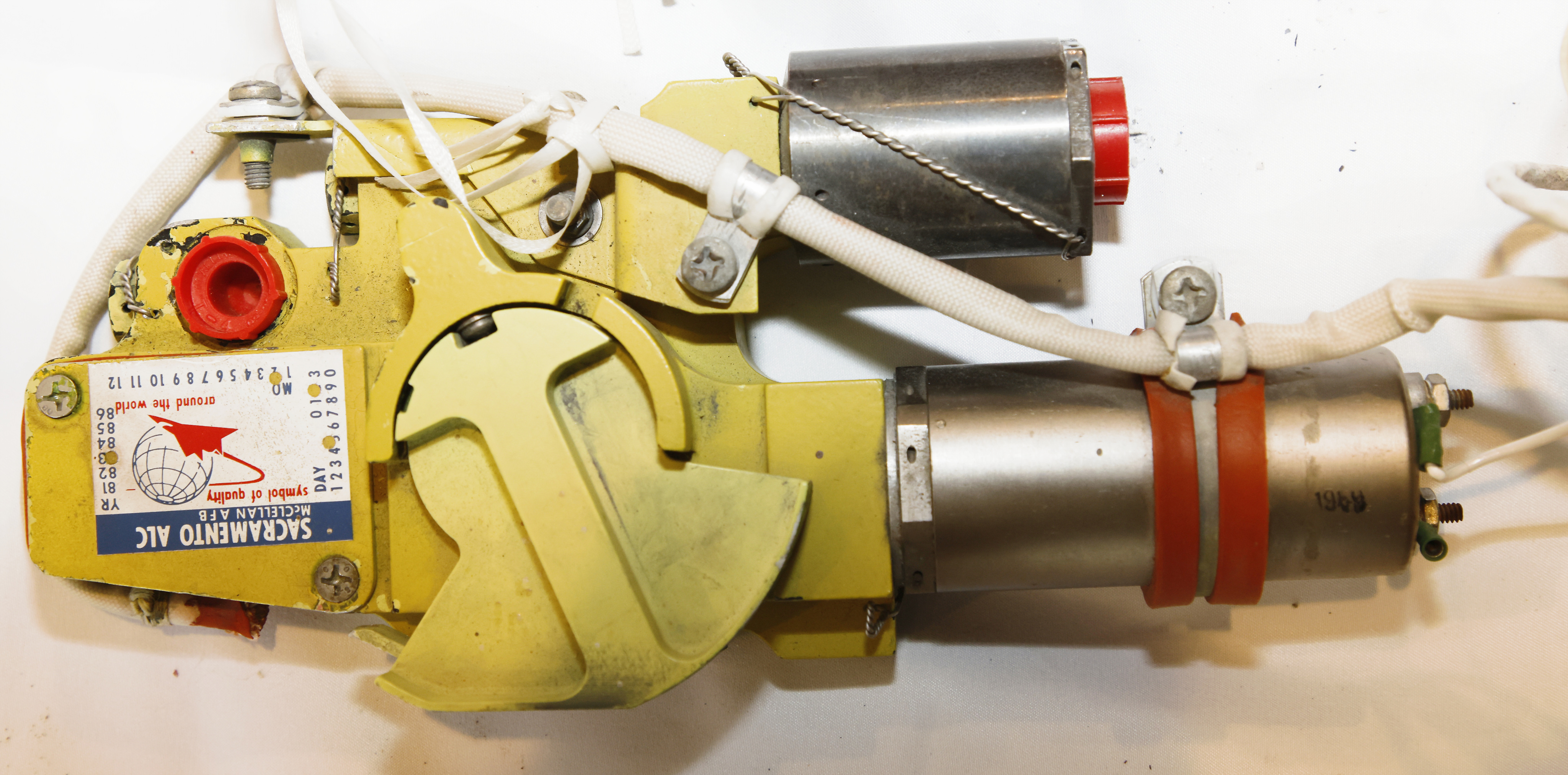
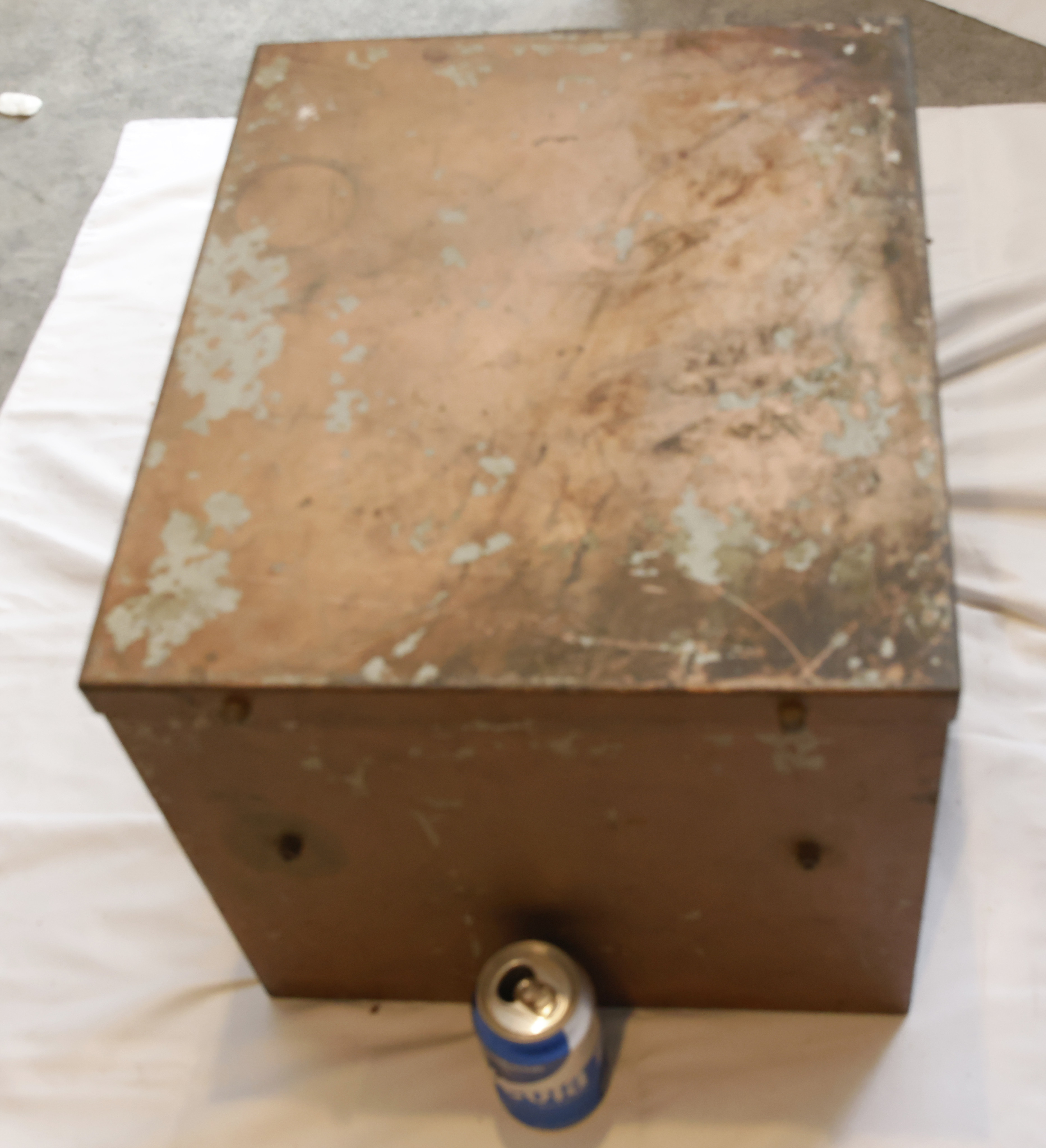
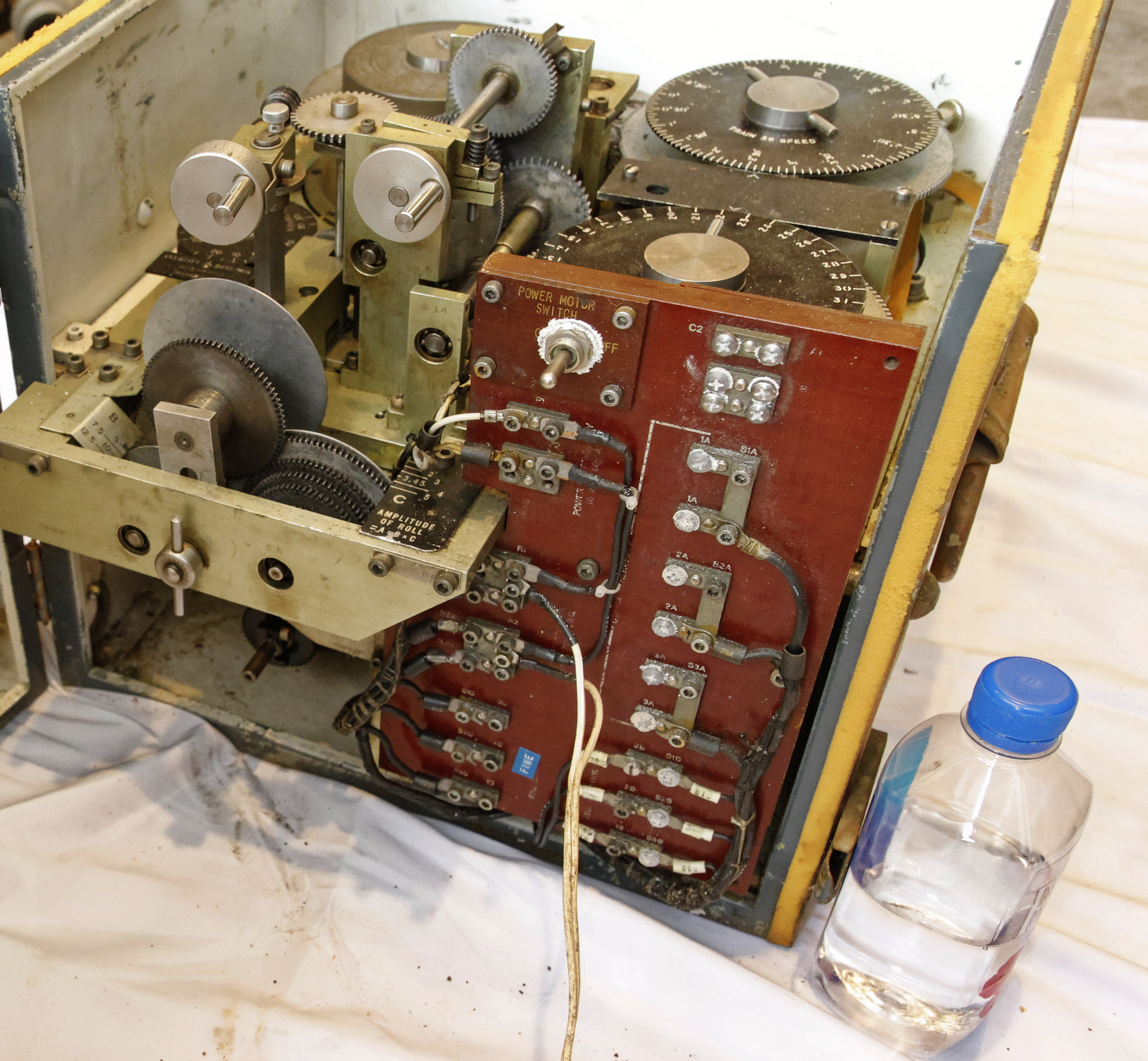
Here is one of my favorite devices: a “K-4” bombing computer. It’s a favorite because:
--It is old (current device has 1954 markings)
--It computes using electric-mechanical analog mechanisms
--It is very complicated, likely impossible to us to reverse engineer
--It is for the military
--It is very unknown!
About the unknown... I can find almost nothing about this device. The closest are two pictures of an earlier device shown in Pictures 12 and 13, as referenced in https://usautoindustryworldwartwo.com/harris-seybold-potter.htm. These pictures show something much more primative than our device, but abviously there is some resemblence. Maybe this is a prototpe and never used, but its high serial number
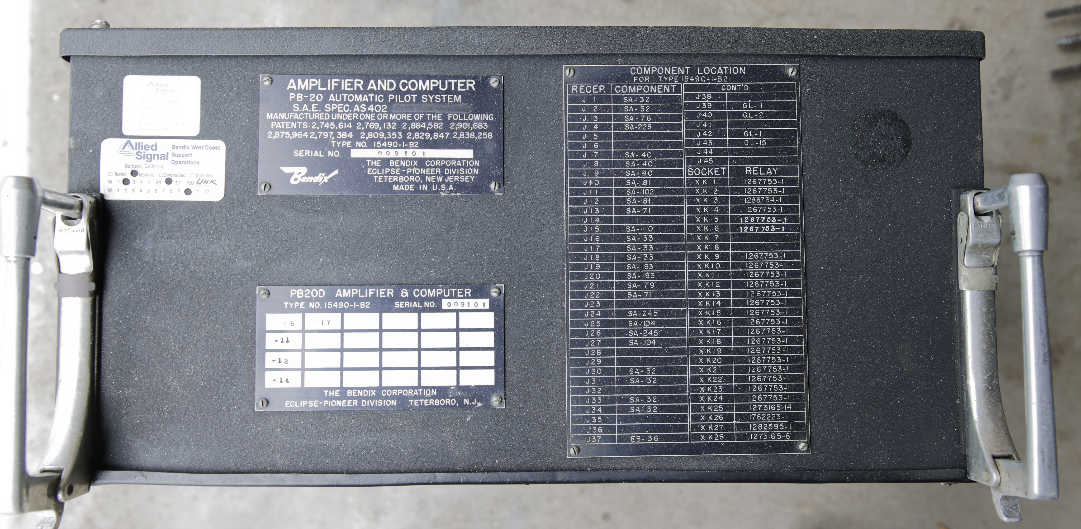
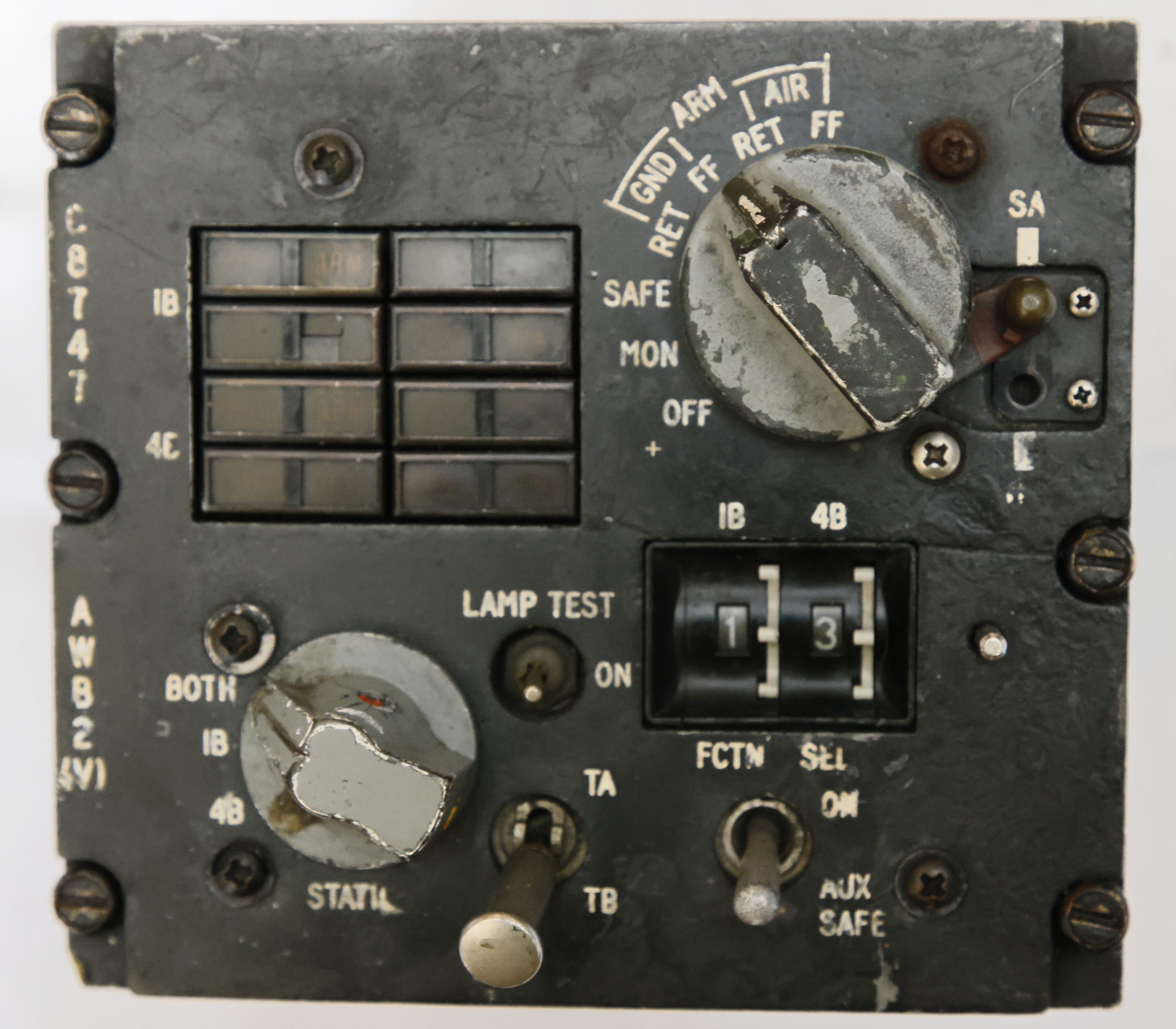
This is the autopilot used on the first major commercial jet aircraft: the Boeing 707. It was also used on the many models and derivatives of the 707 (such as the Boeing 720) and the many derivative military versions: the Boeing E-3, C-137, KC-135, the Northrup Grumman E-6 and E-8, and others. A derivative of the PB-20 was also used in the first major English-developed jet passenger plane, the Vicors VC-10.
As is generally true with most aviation electronics, once qualified, they live a long time. Our unit, as shown in Figure 2, was last repaired in 10/1990, almost 32 years since the design first flew commercially. Its serial number of 9101 also hints at long life.
Due to the high altitude, the fast speed, and the sweepback wings of the 707 vs. earlier piston-driven planes, the 707 autopilot had to deal with new challenges vs. eatlier types of autopilots. However, since the first commercial flight of the 707 was in late 1958 so this device features primitive 1950's technology including no tubes and very few transistors.
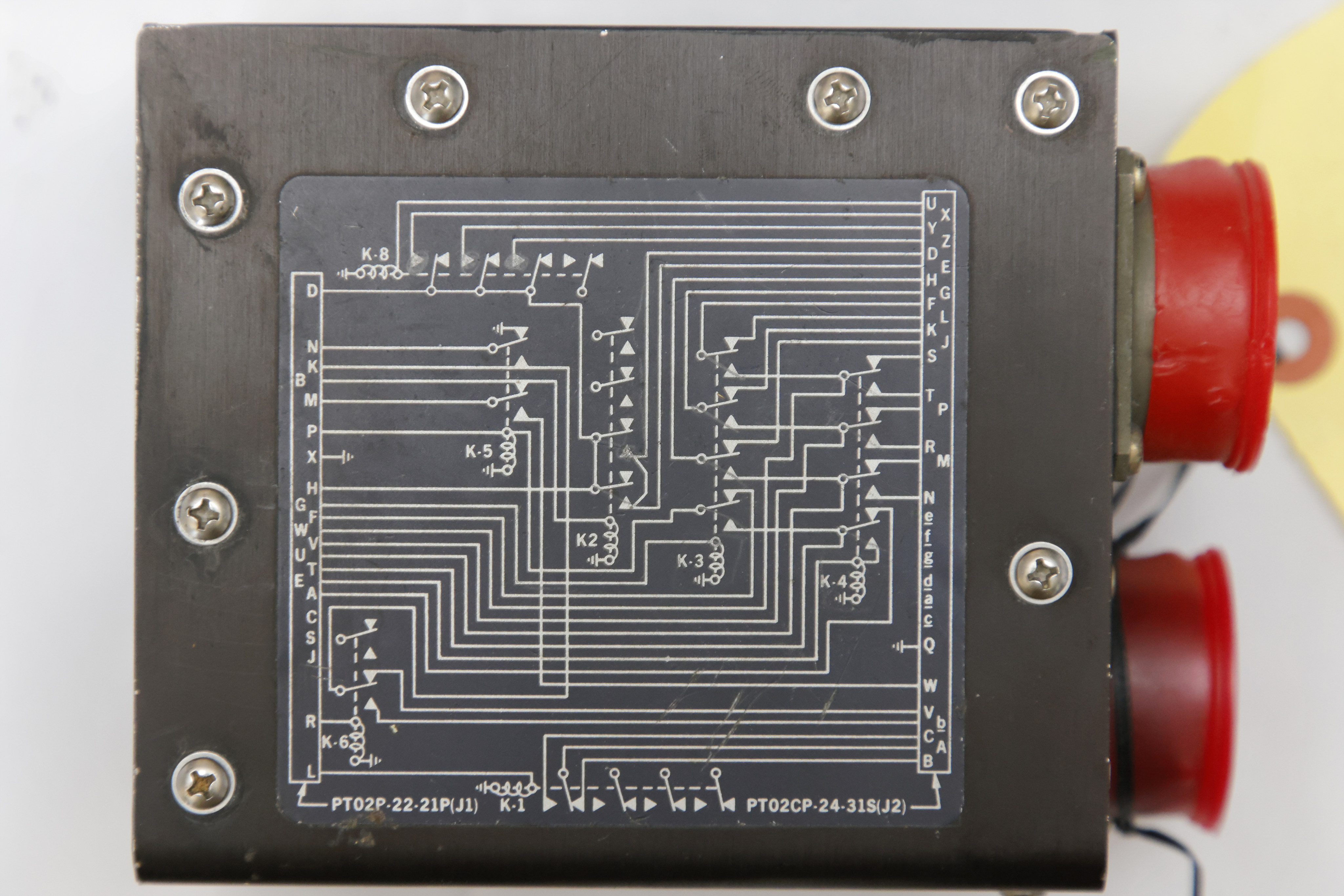
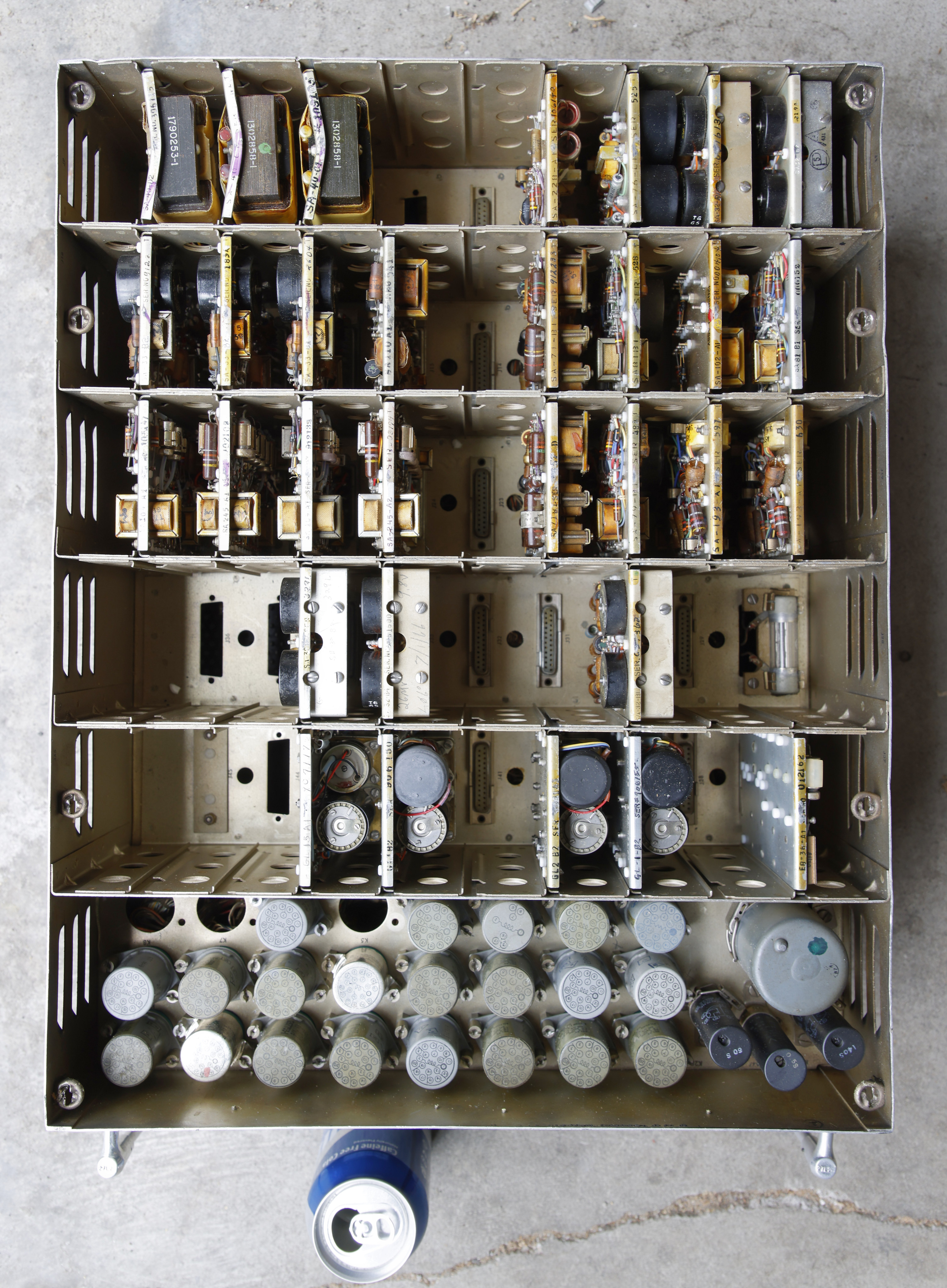
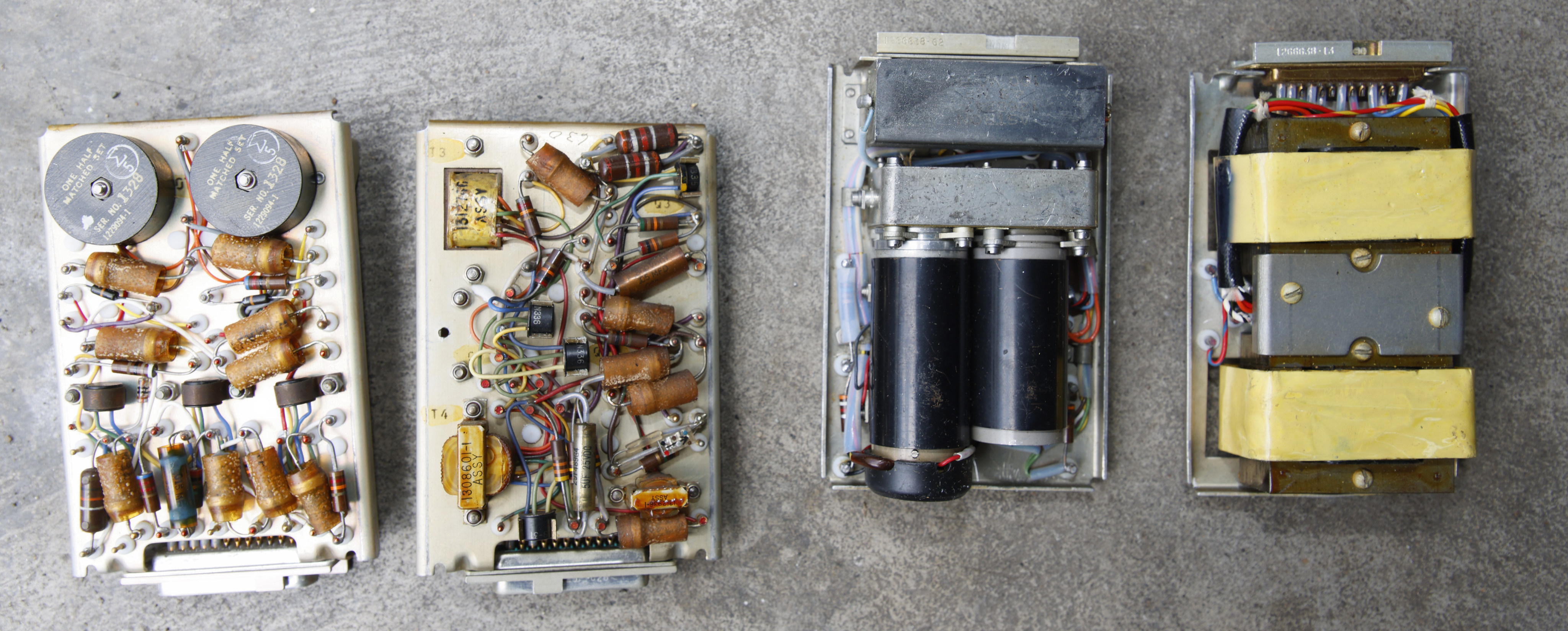
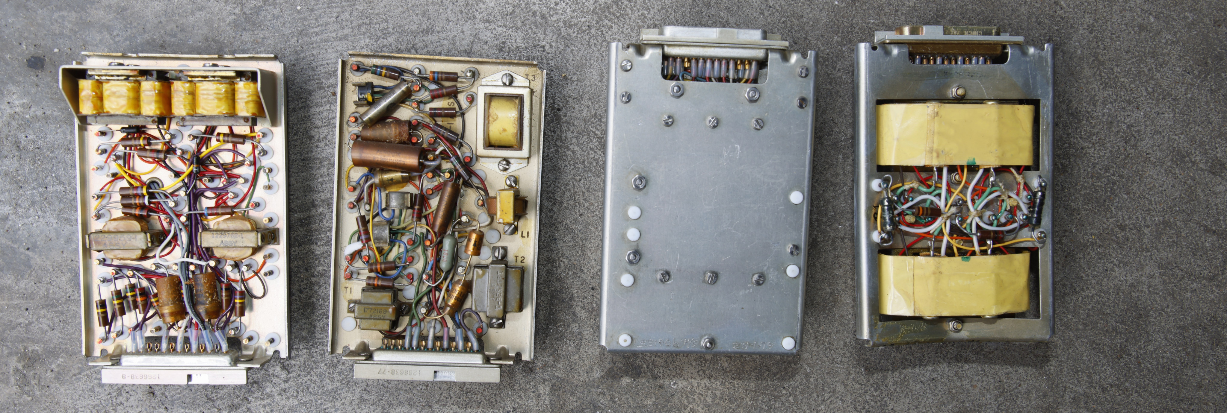
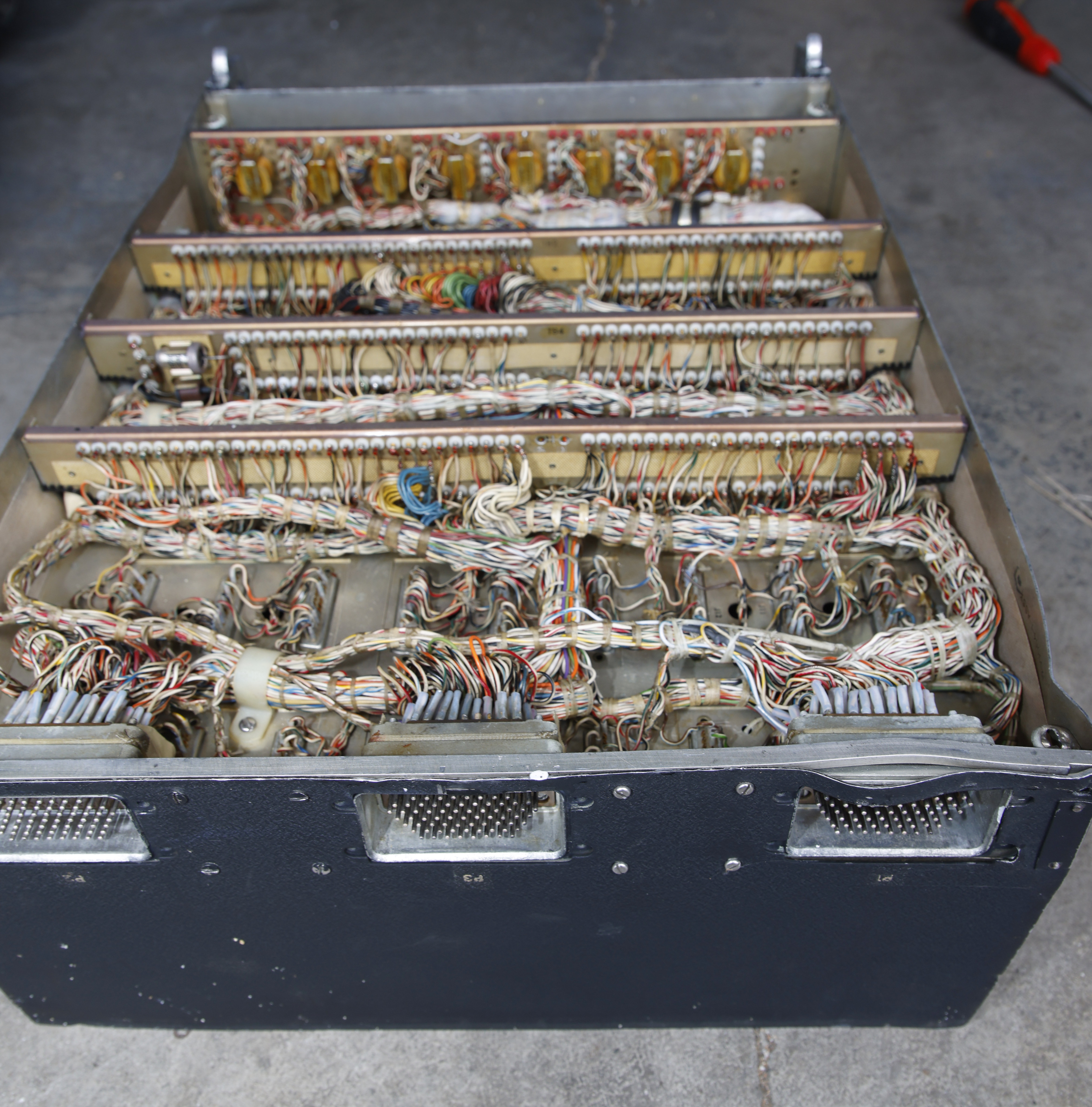
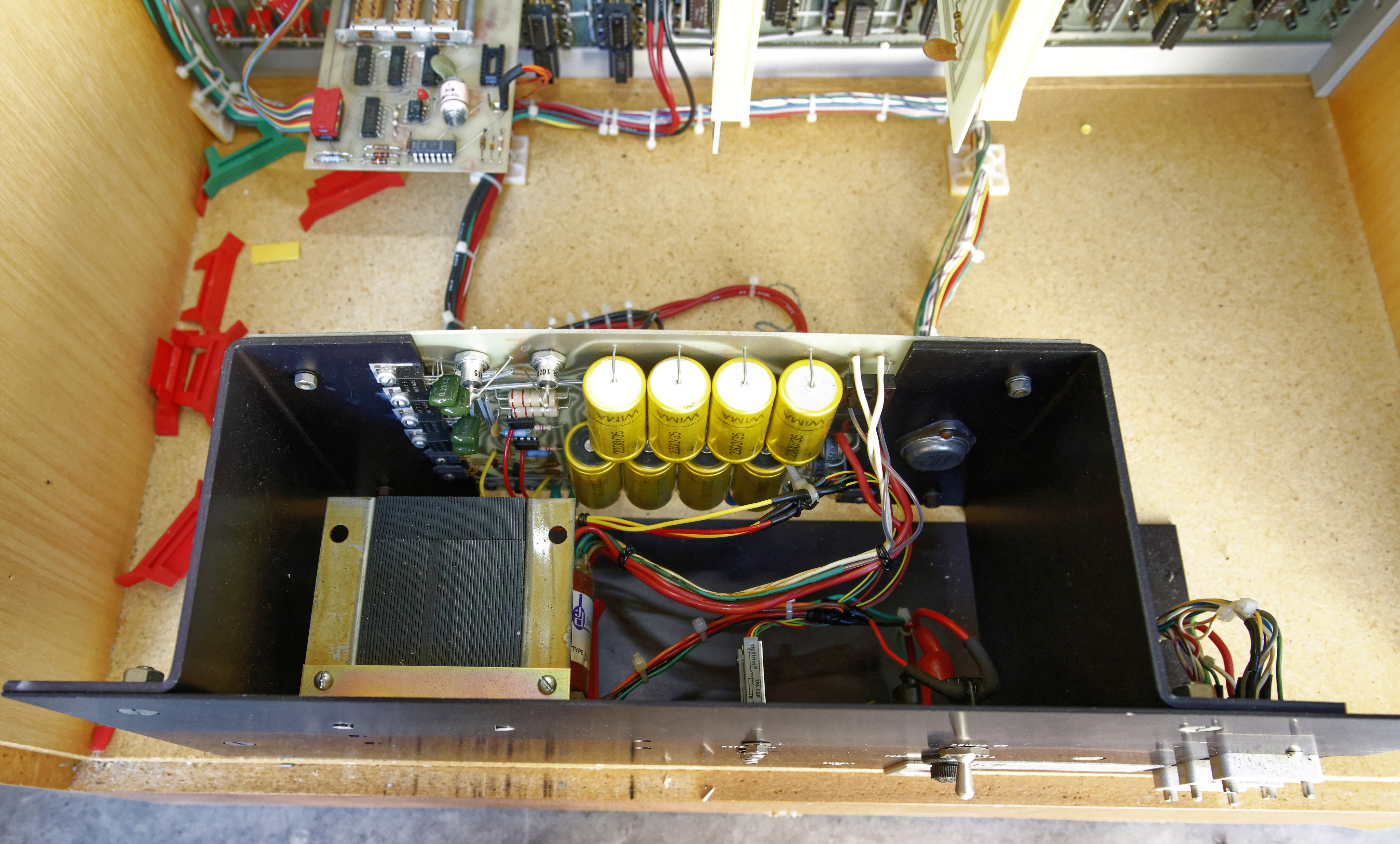
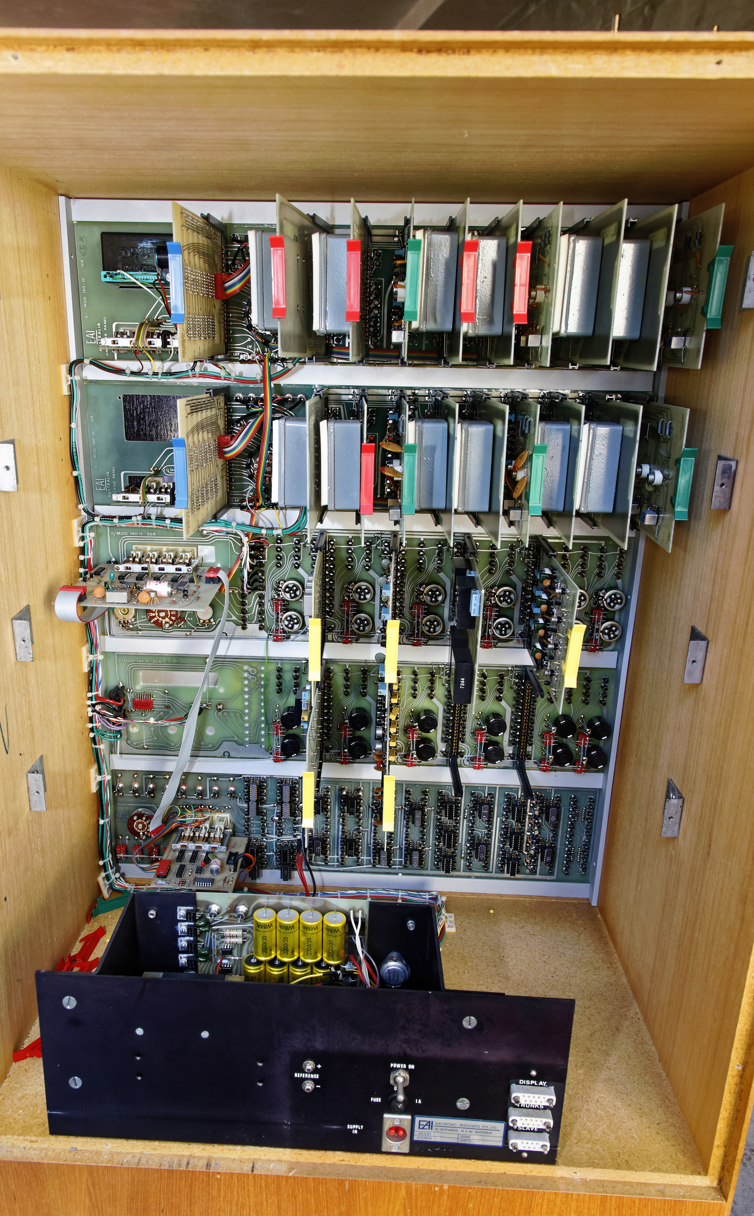
Figure 1 is the looking down at the PB-20. The tube-like shapes near the bottome are not tubes but rather are relays. Otherwise, the logic is contained on about 30 sepeparate plug-in cards. Both sides of selected card examples are shown in Figures 3 and 4.
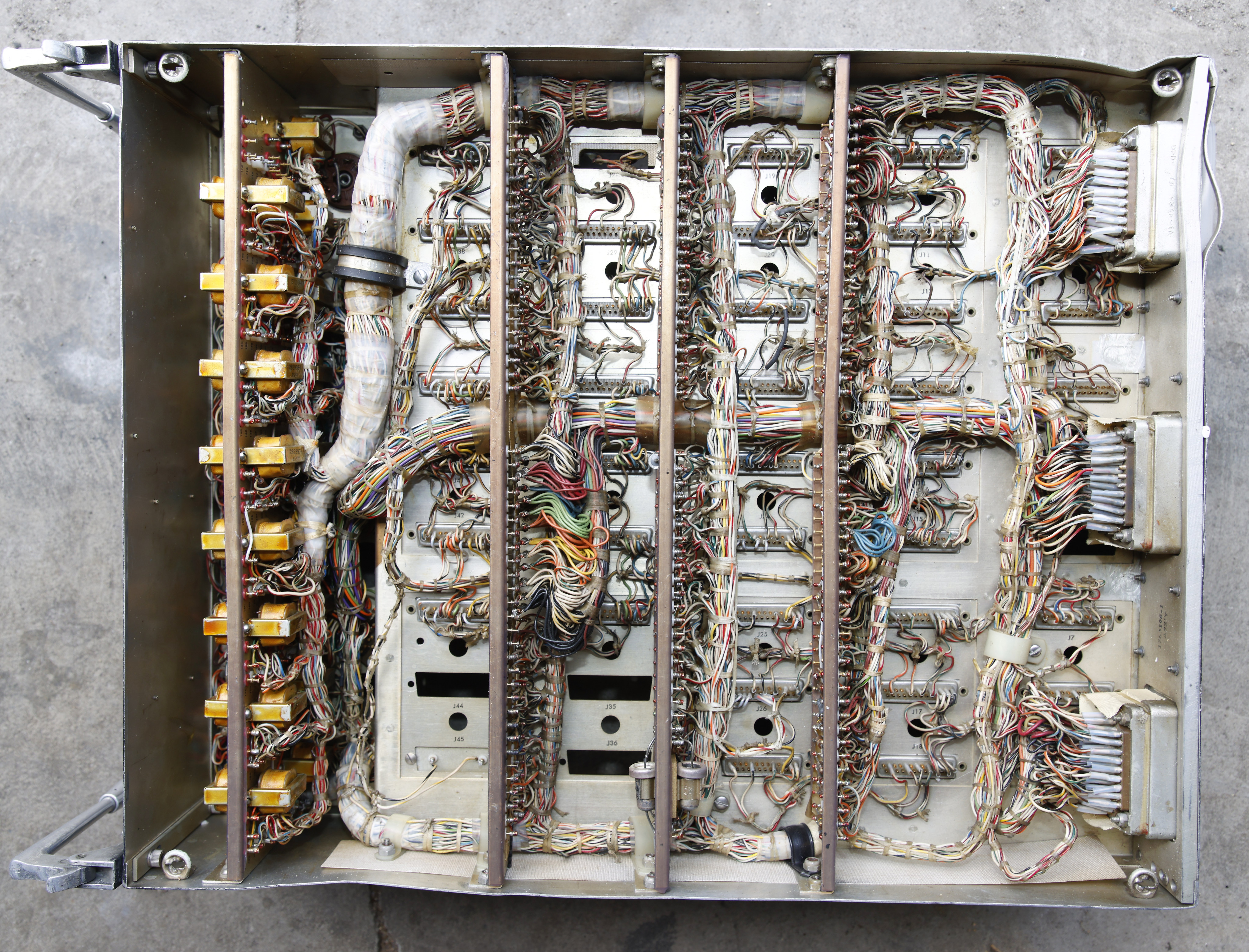
The bottom view (Figure 5) is a rats-nest of wiring, with the external I/O attached to three 58-pin ports, as also show in Figure 6.
I have flown on a 707 and if I could have seen the ad-hoc physical structure and wiring of its PB-20, I might have had second thoughts. It's hard to imagine that the primitive technology and assembly style shown in Figures 3, 4, and 5 could be "life-critical."
This document discusses some details of the PB-20 design (called "PB20" in this doc).


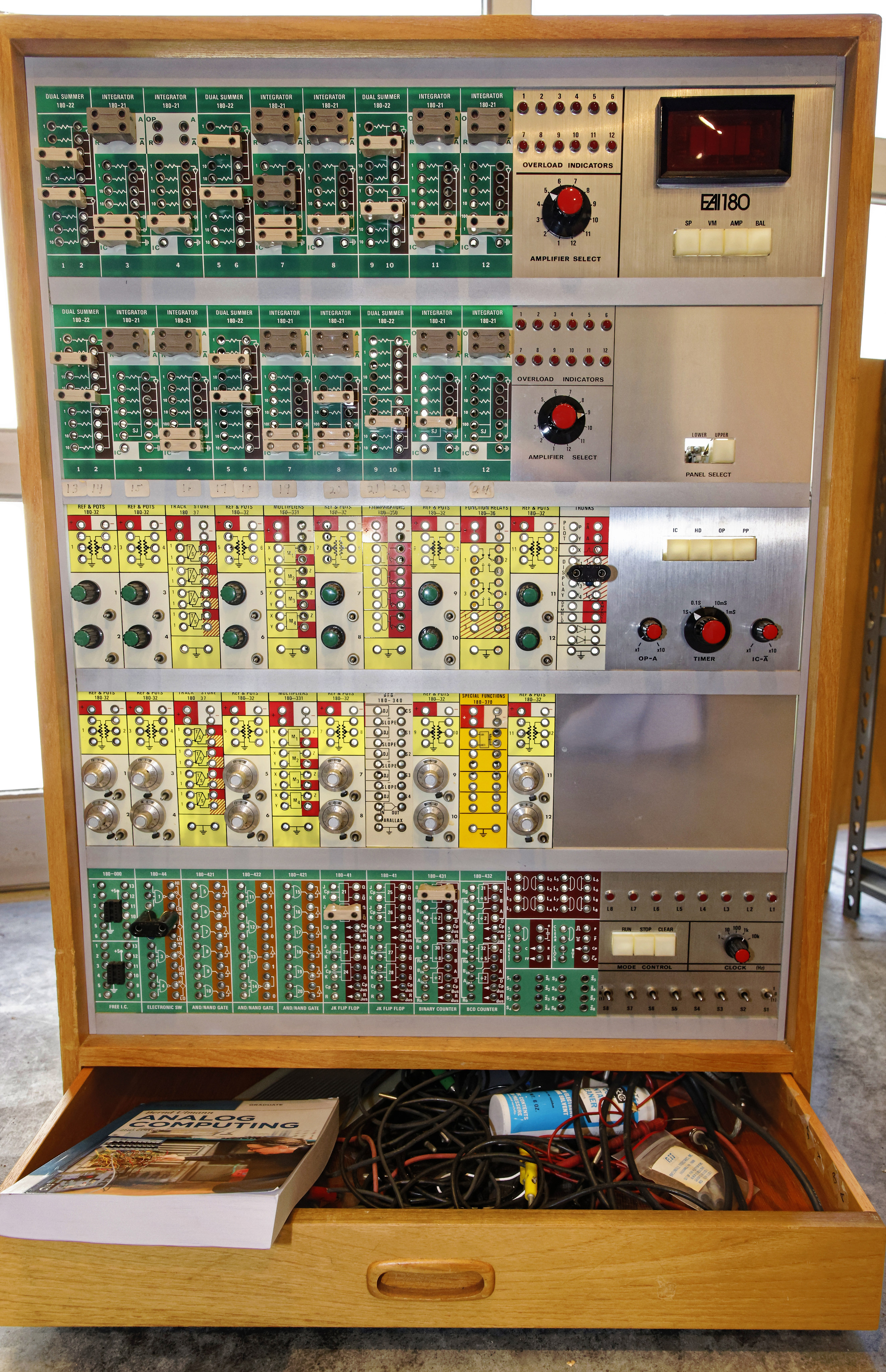
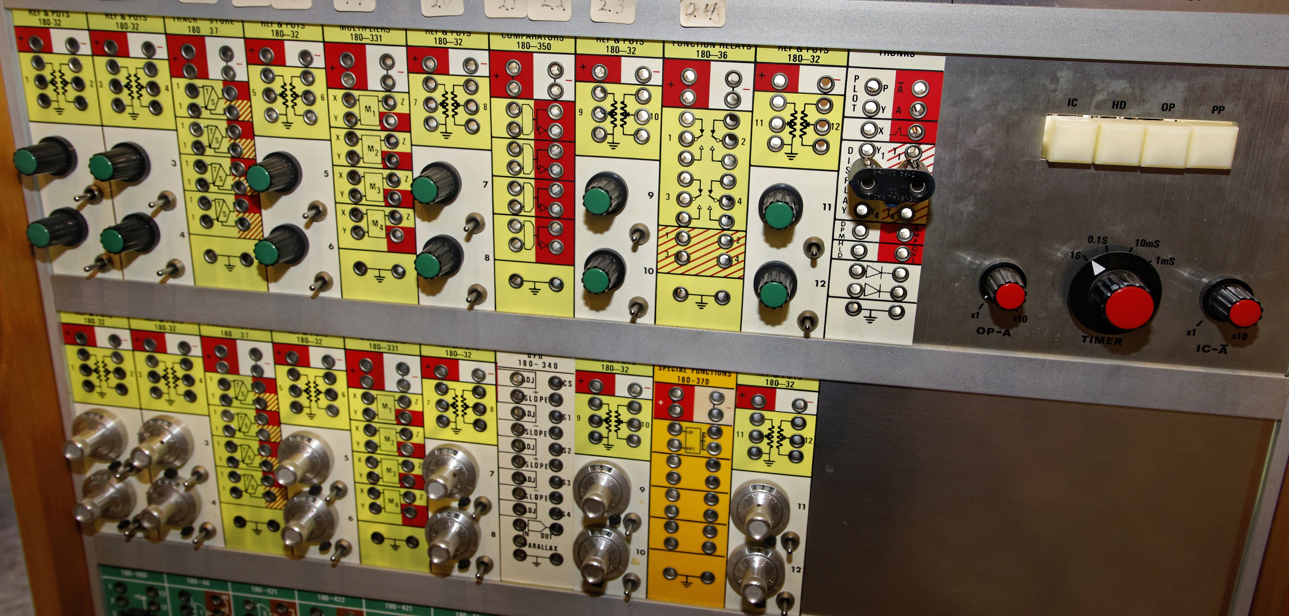

I truly love analog computers! And, my site has lots of them including the specialized military devices. If you want to know more about analog computers (including their history), how they work, or why they are still useful, I highly recommend the book sitting on the slide-out tray of connectors: "Analog Computing: 2nd edition" Bernd Ulmann. See this reference manual.


OK, I know, I know! I already have one of these wonderful fire-control computers! But, since a B-29 had five of these (one for each sighting location, all tuned slightly different), it seems only right that the my museum has several. And, I just can't resist this great 1940-ish technology.
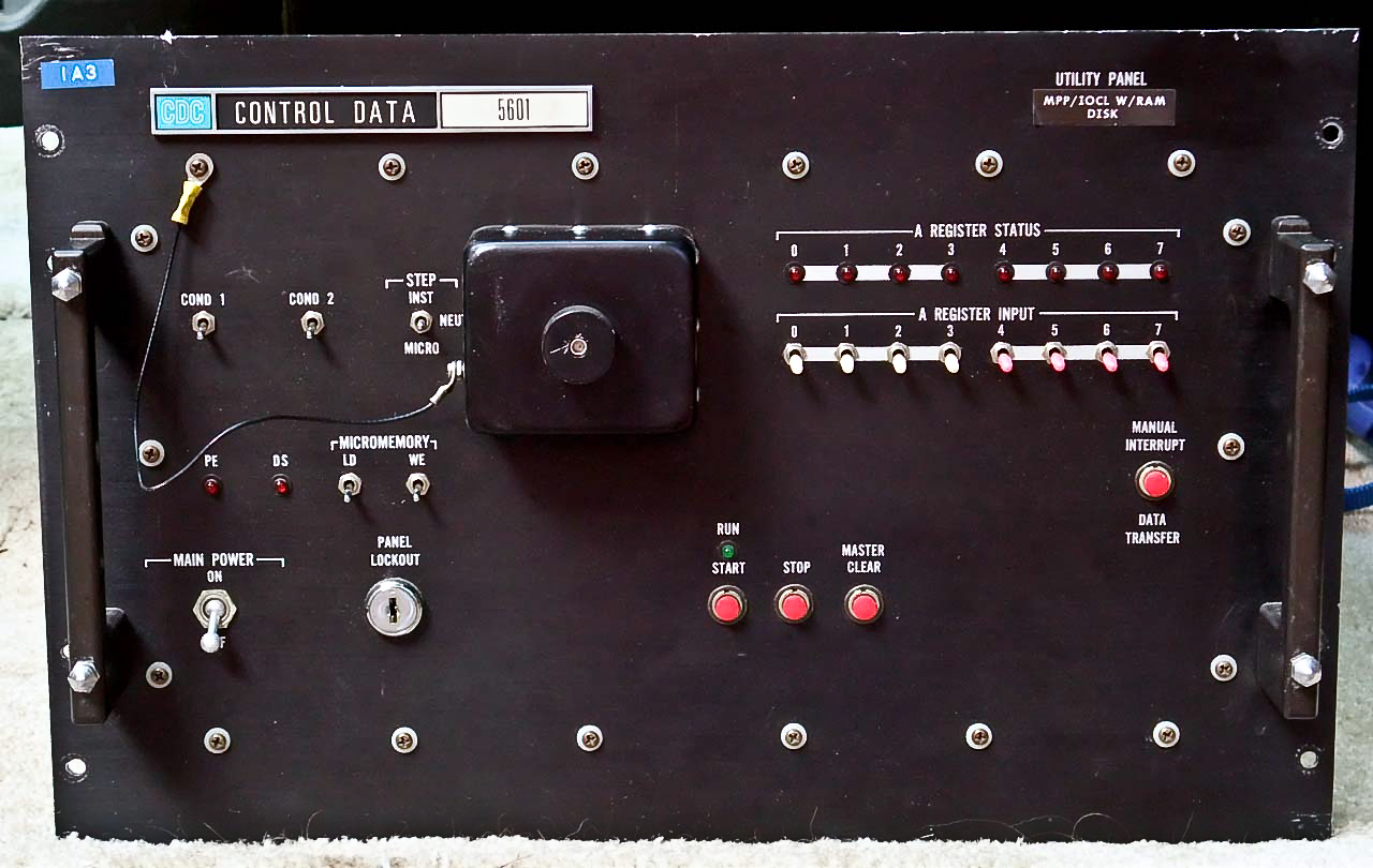
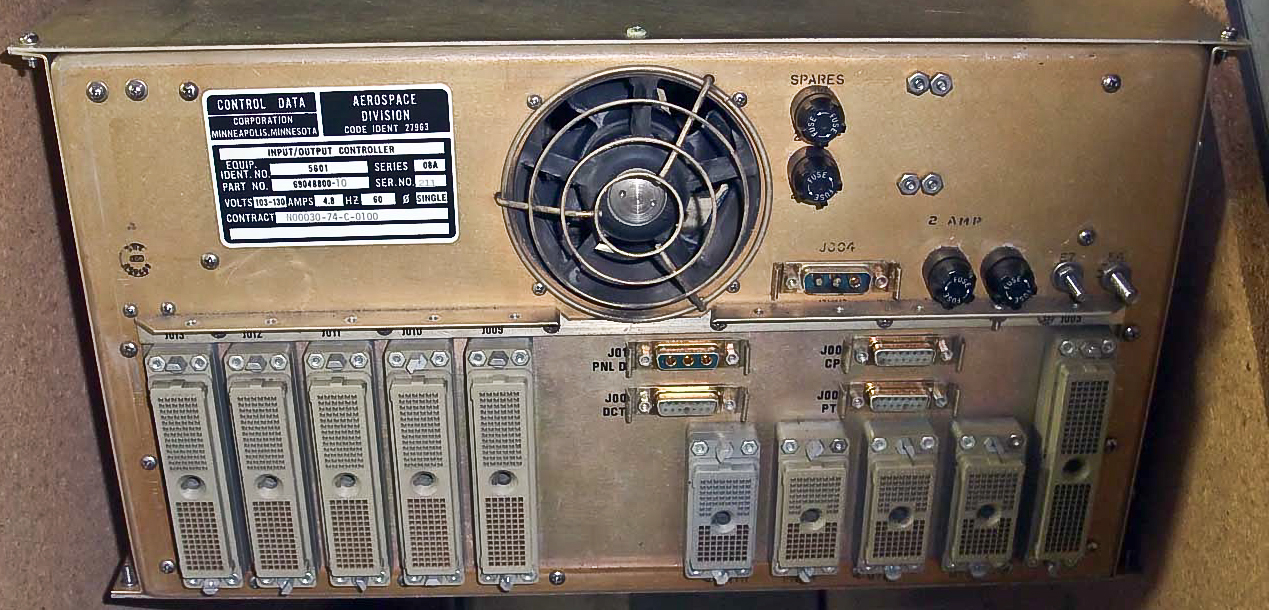

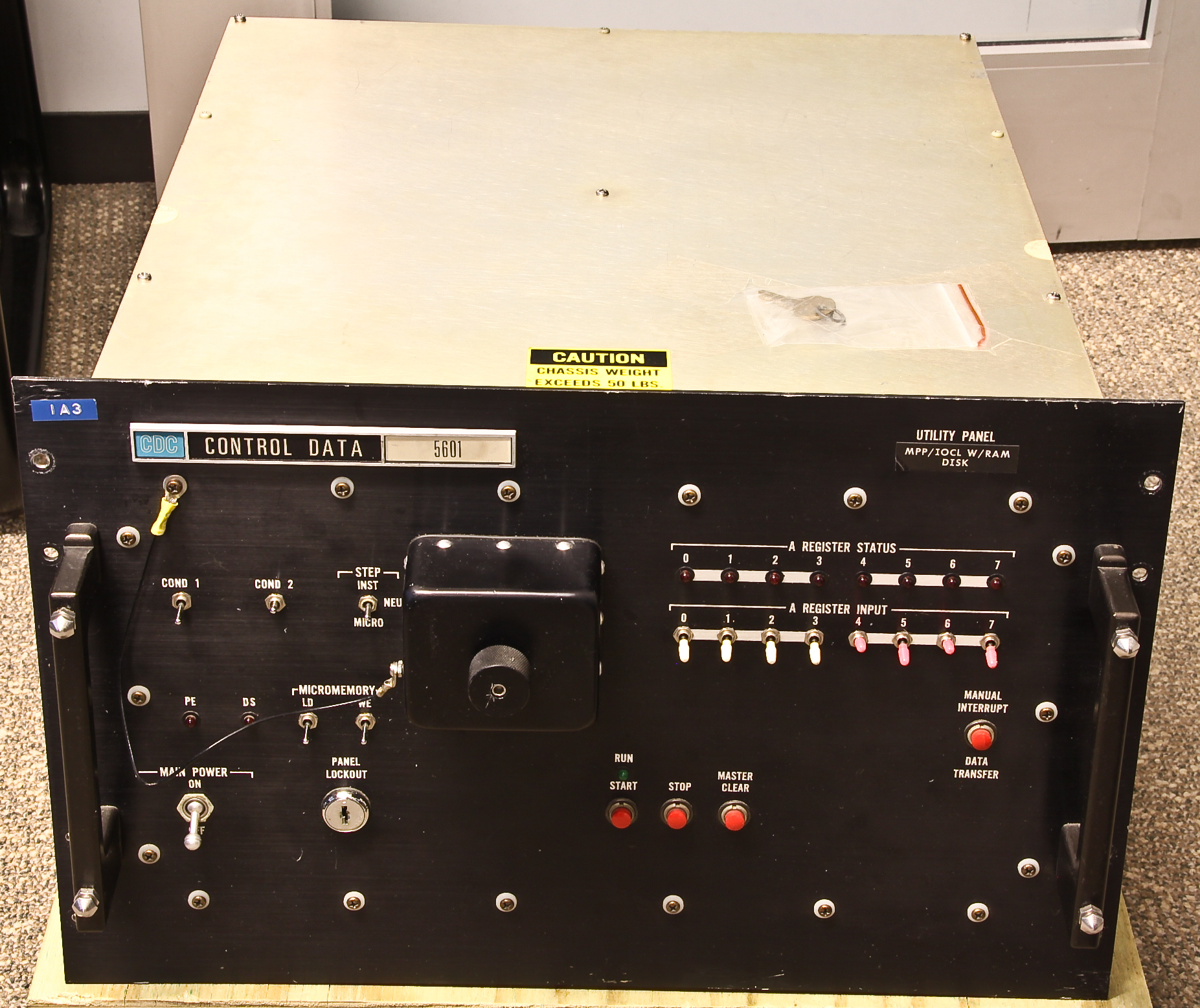
Here’s a “modern” (last maintenance on our device is dated 1977’s, that’s late for our collection) mini-computer from CDC (Control Data Corporation), one of the early leaders in computers.
In particular, ours is labelled as an “input/output controller”, released by the “Aerospace Division” of CDC. Bitsavers has pictures that look just like ours as well as the hardware reference manual, which identifies the 5601 as a “16-bit processor.”
These devices were used in military-type control applications such as identified in this description of an Army “Tactical Fire Direction System” that used several the 5601 instances as well as other members of the 5601 family.
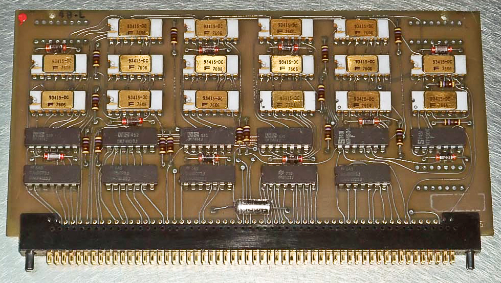
It turns out that the internal design is very similar to some computers I worked on at IBM in the 1970's! It uses a microprogramming control approach which “executes” very simple microinstructions that typically could be used to “emulate” a more normal instruction set. This microprogramming approach was very common on processors of that era, including, of course, the IBM System/360 family and other IBM processors of the 1970s. According to the reference manual, loading a register takes 2.0 us (microsecond) and an register-register add takes 1.3 us. This about 6,000 times slower than the tiny embedded controller that I am working on at this moment.
The 32-bit microinstructions (“nanocode”) were stored in a writable “control-store” memory (I’m using terms more familiar to IBM) that had a 80-ns access time. Each microinstruction could perform up to four operations: ALU, memory, I/O, and choose the next microinstruction location. Again, this is very similar to how many computers of the 1960’s and 1970’s were designed.
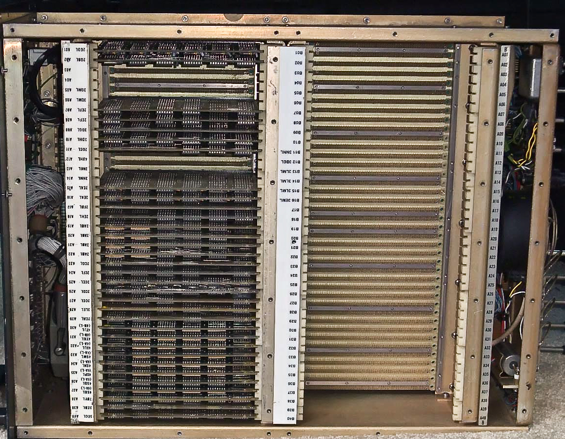
We seem to have only the processor itself, not the memory cards.
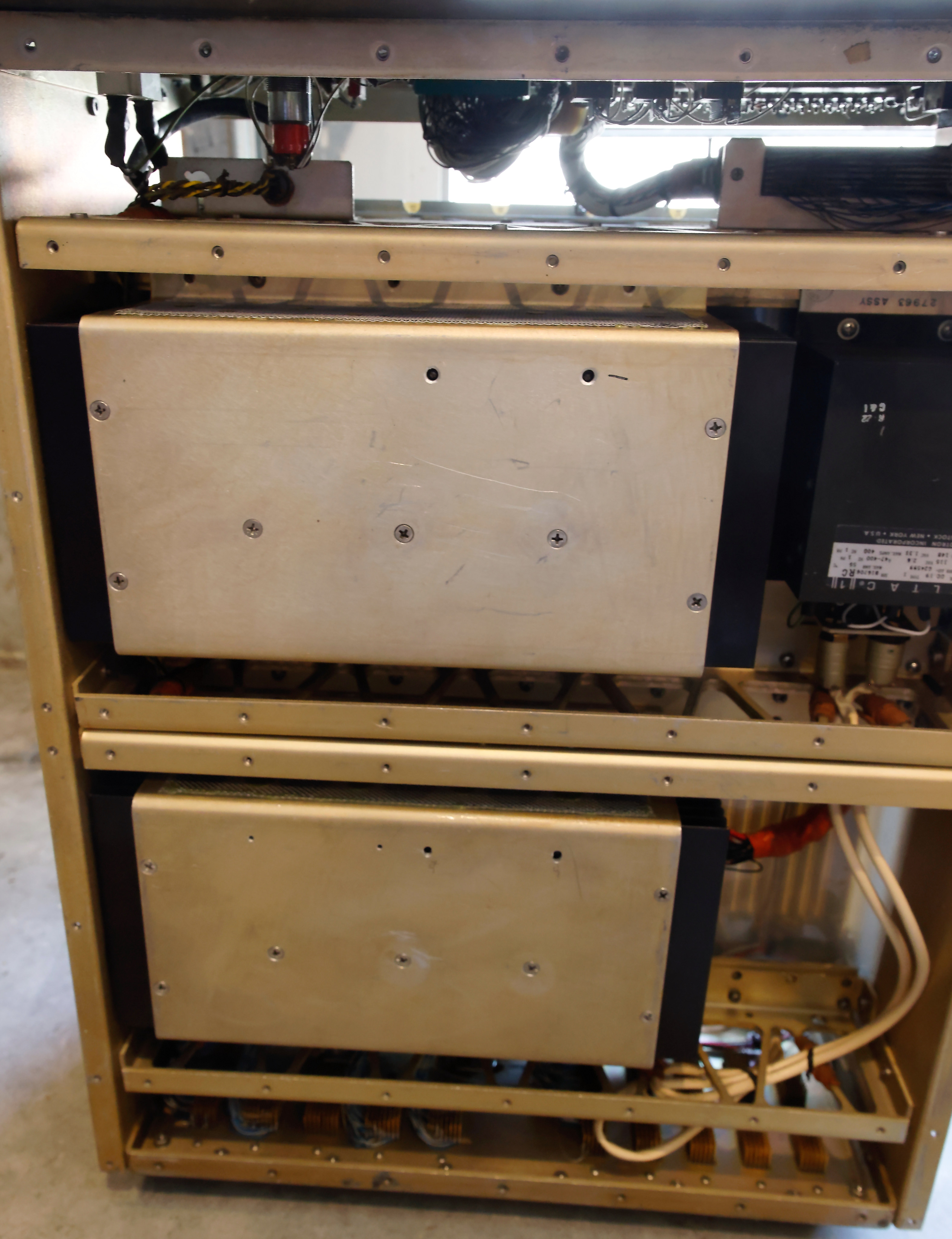
The two power supplies (on the underside of the processor card area) each produce 56 amps of 5V. That is a lot!


Here is a "ballast computer" from a submarine.