Glenn’s Computer Museum |
| Home | New | Old Military | Later Military | Analog Stuff | IBM Stuff | S/3 Mod 6 | S/32 | Components | Encryption | Misc | B61 |
change log |
contact me |
![]()
Glenn’s Computer Museum |
| Home | New | Old Military | Later Military | Analog Stuff | IBM Stuff | S/3 Mod 6 | S/32 | Components | Encryption | Misc | B61 |
change log |
contact me |
![]()
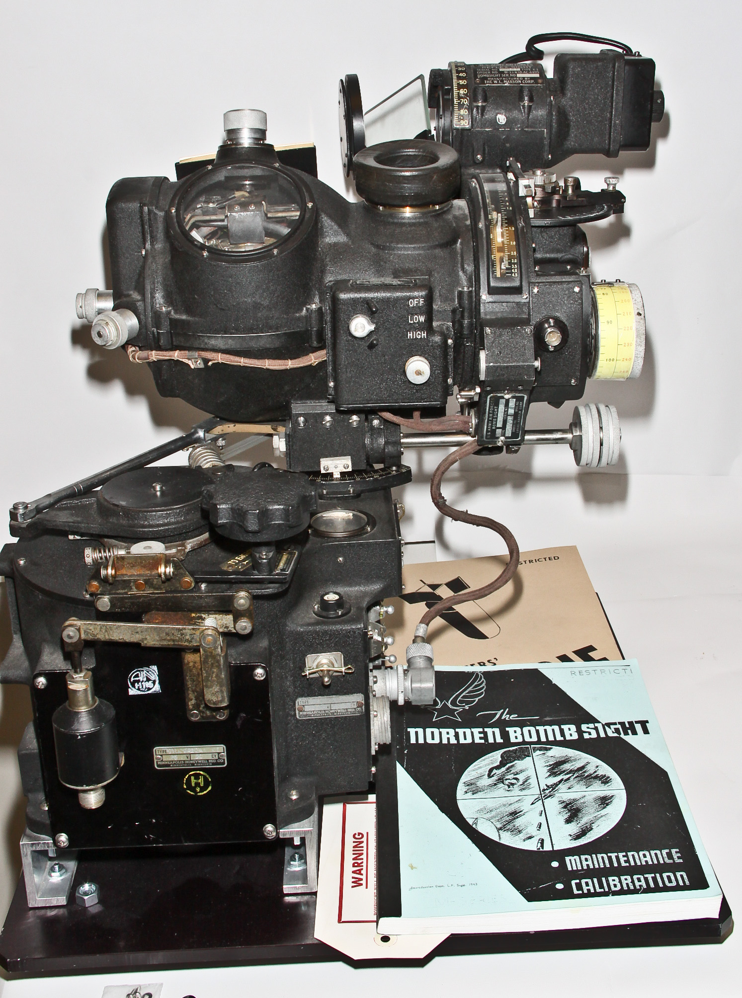
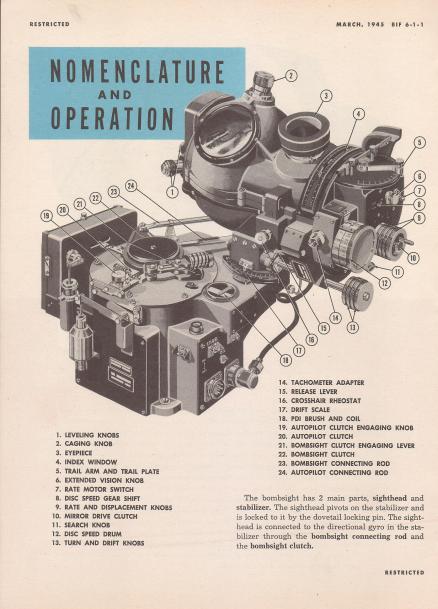
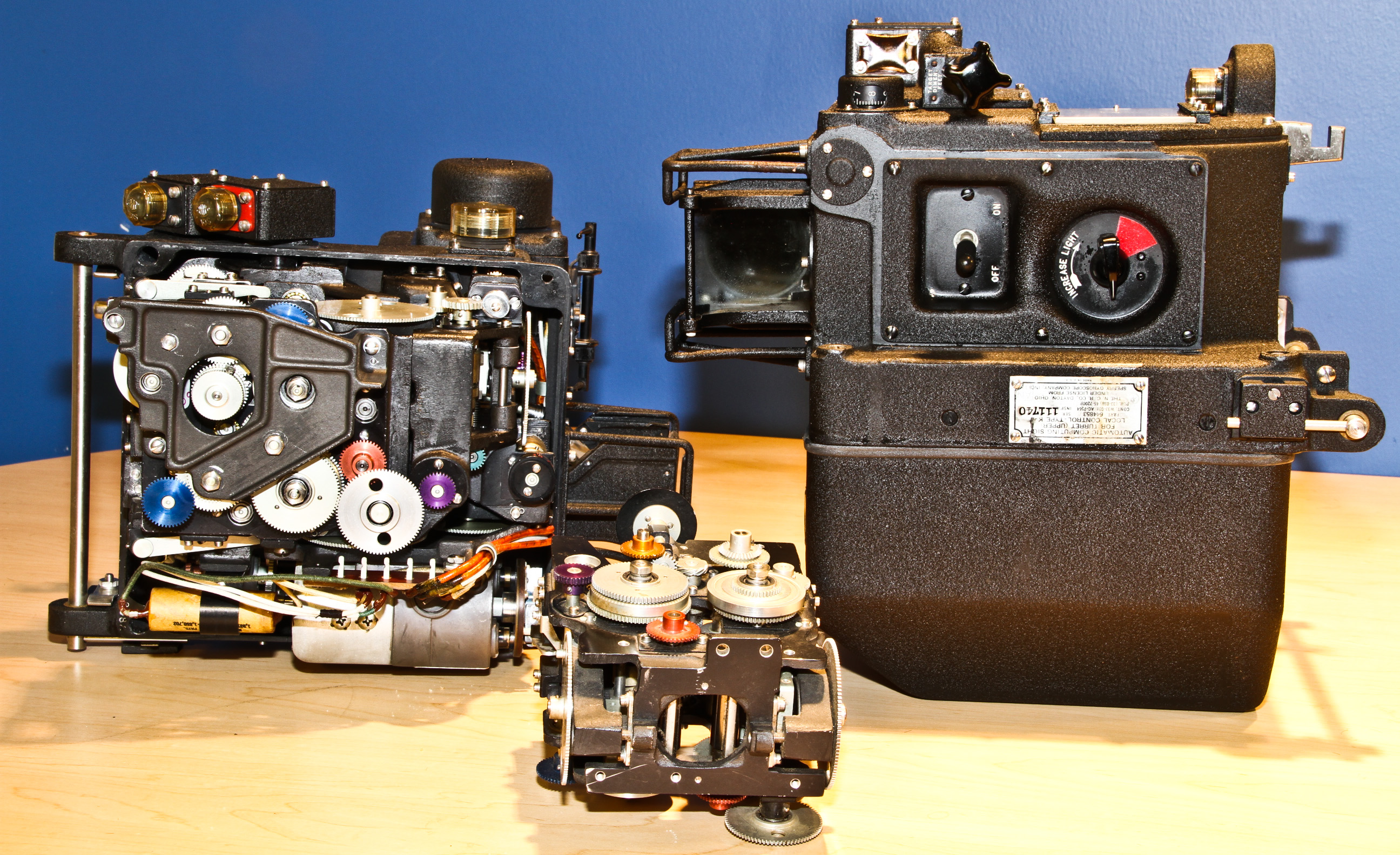
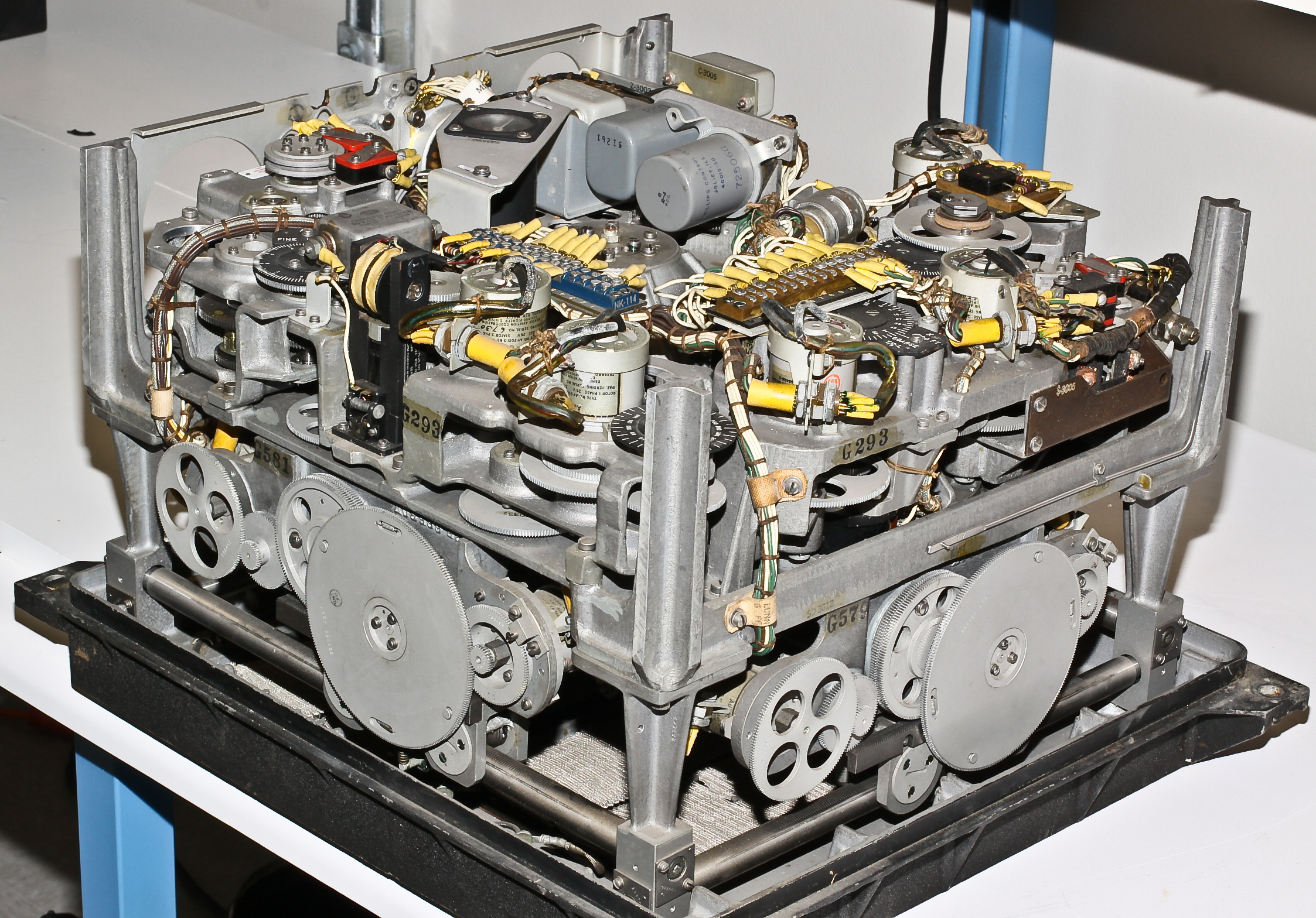
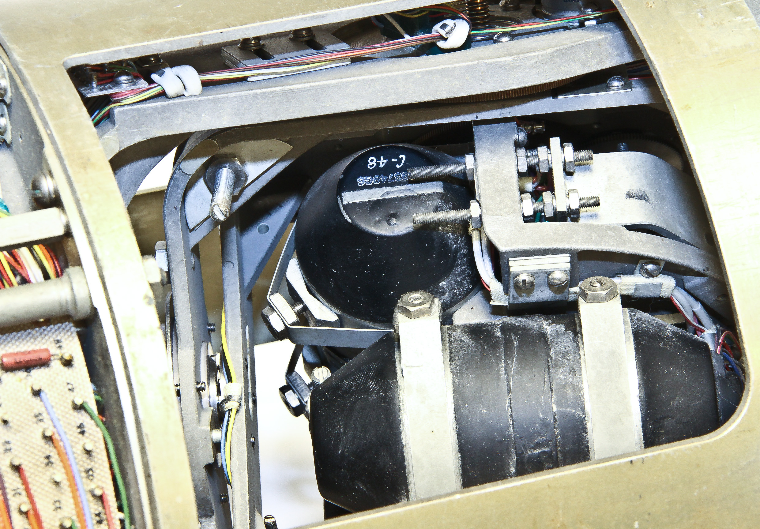
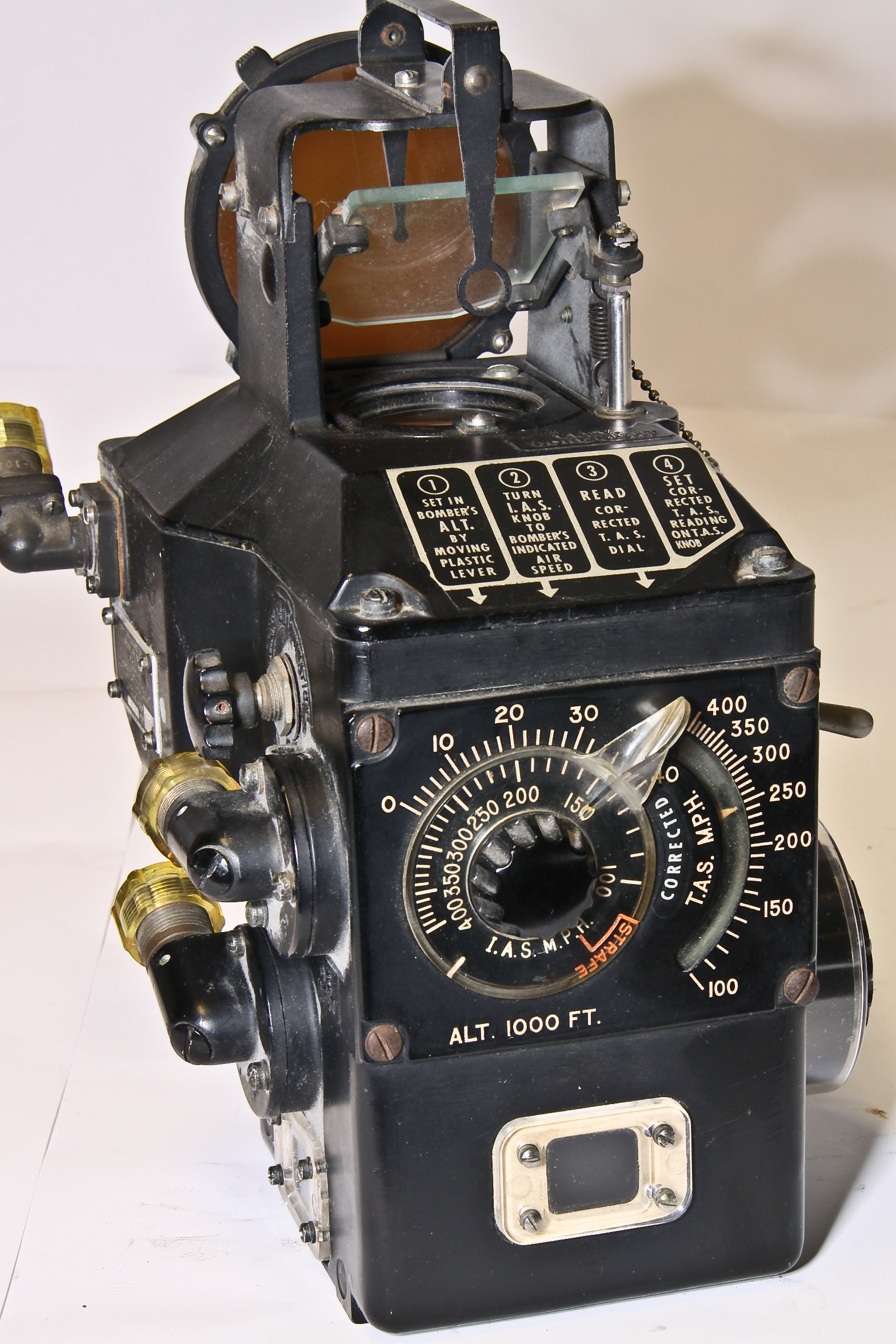
One of the most famous devices of WW II is the Norden bombsight, often mentioned along with radar and the atomic bomb as the most important technologies in winning the war. There is lots of good reference material on the web, including this great site about bombsights.
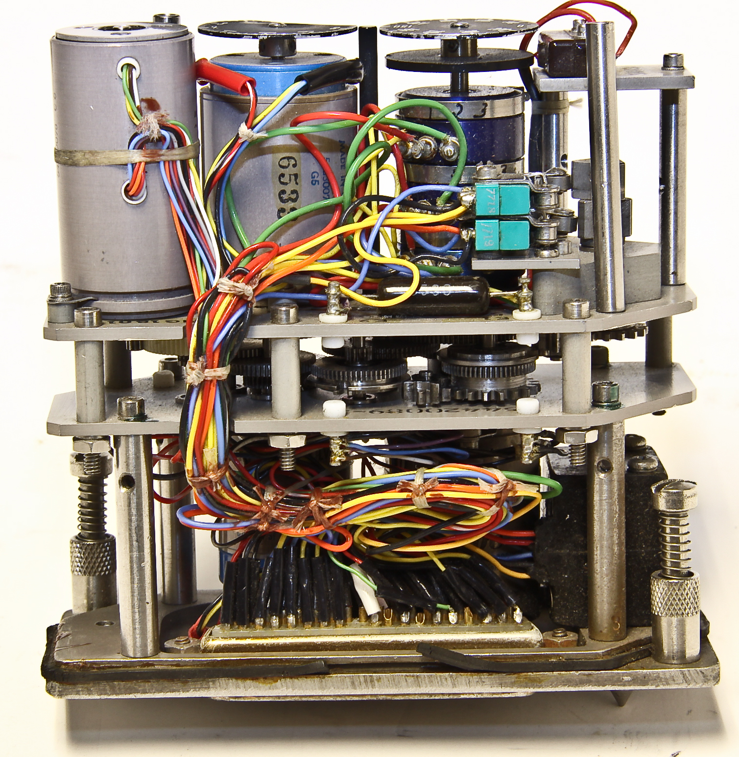
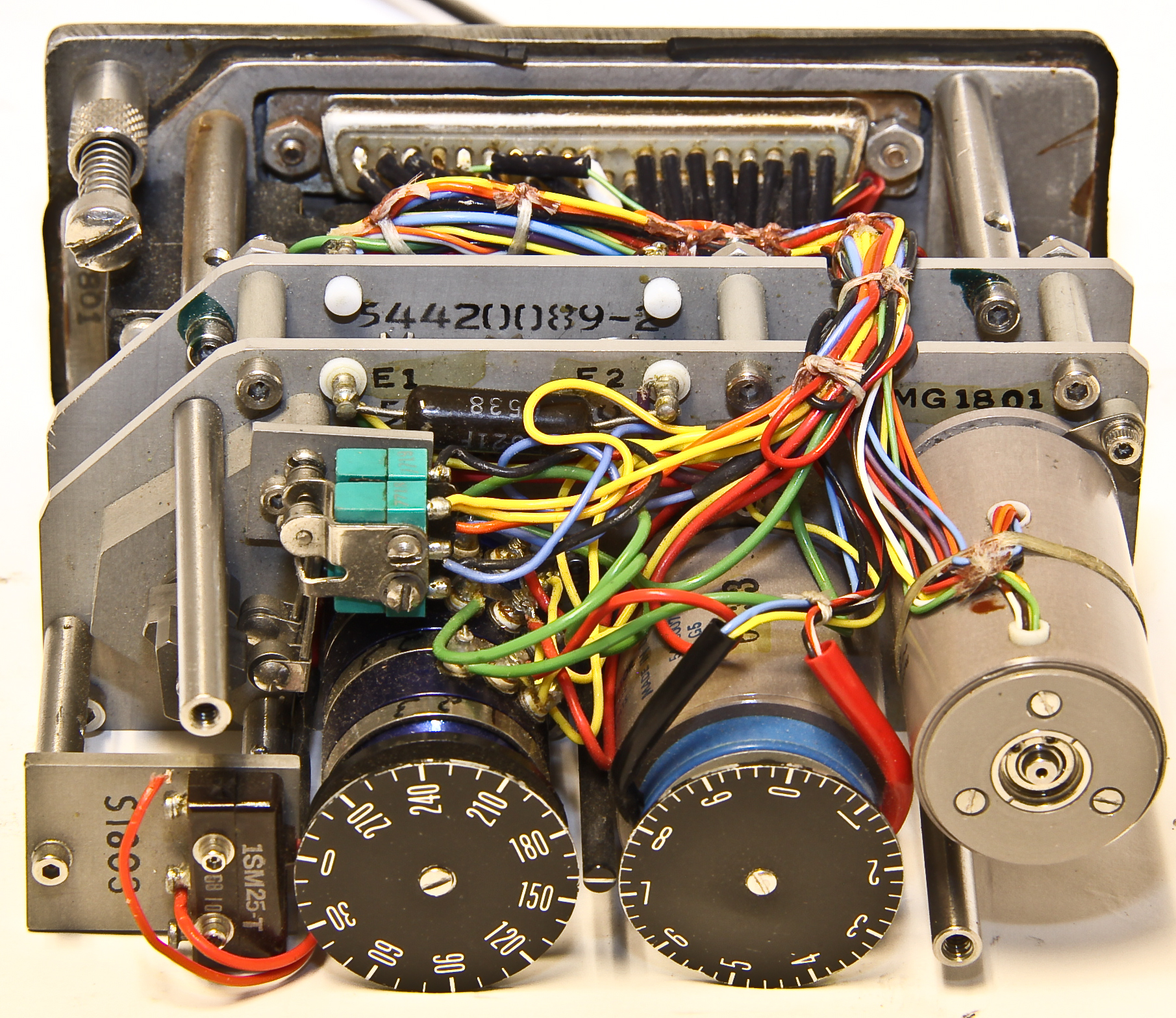
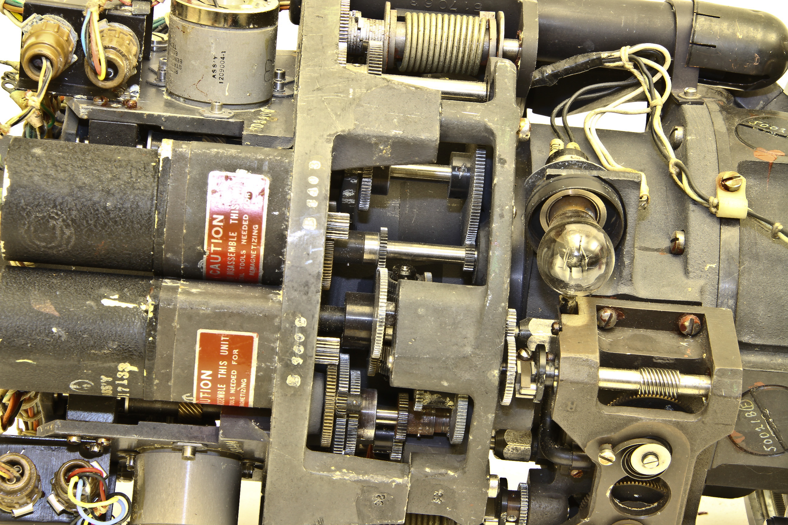
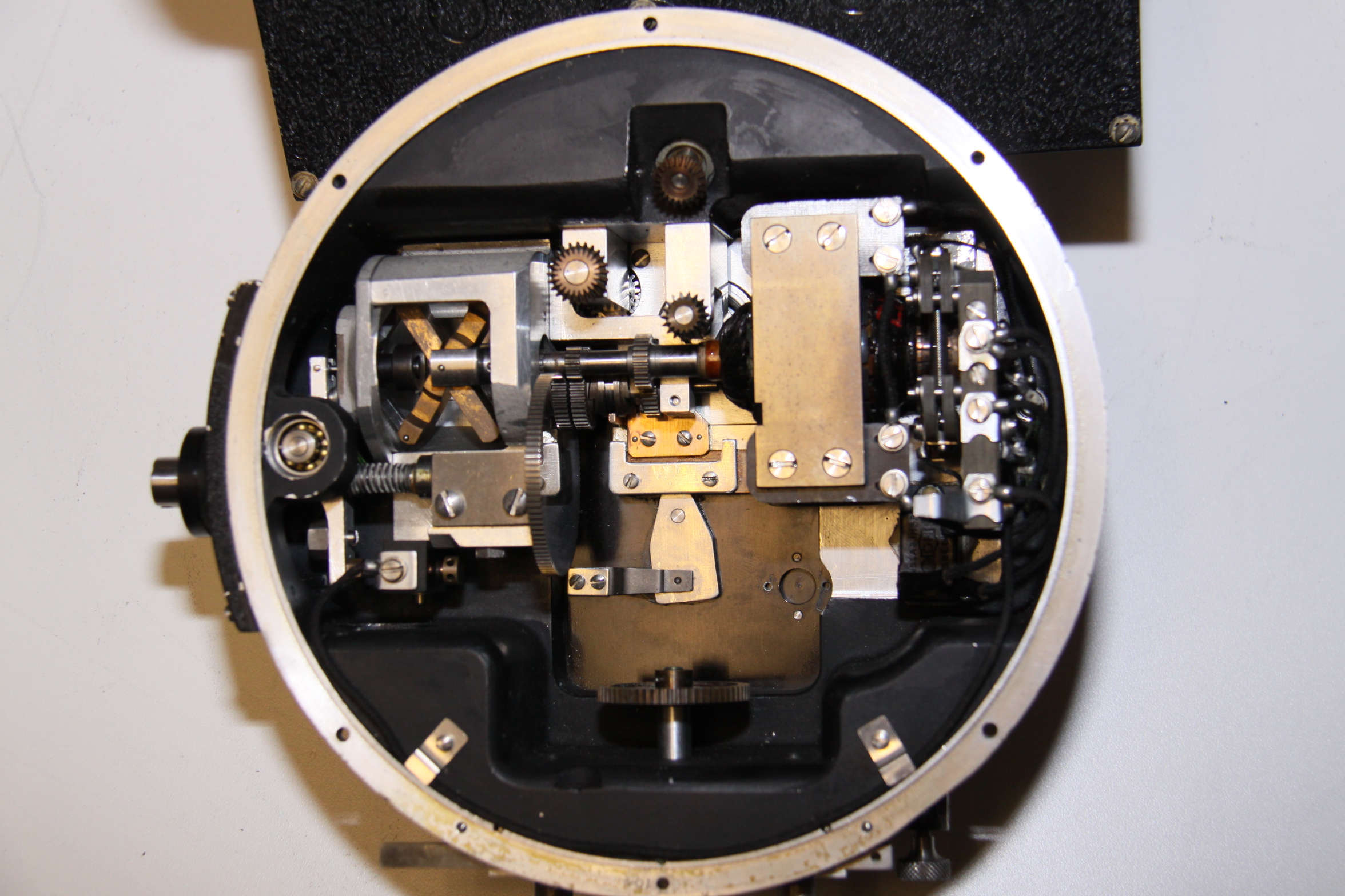
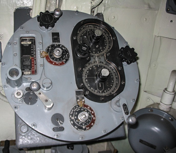
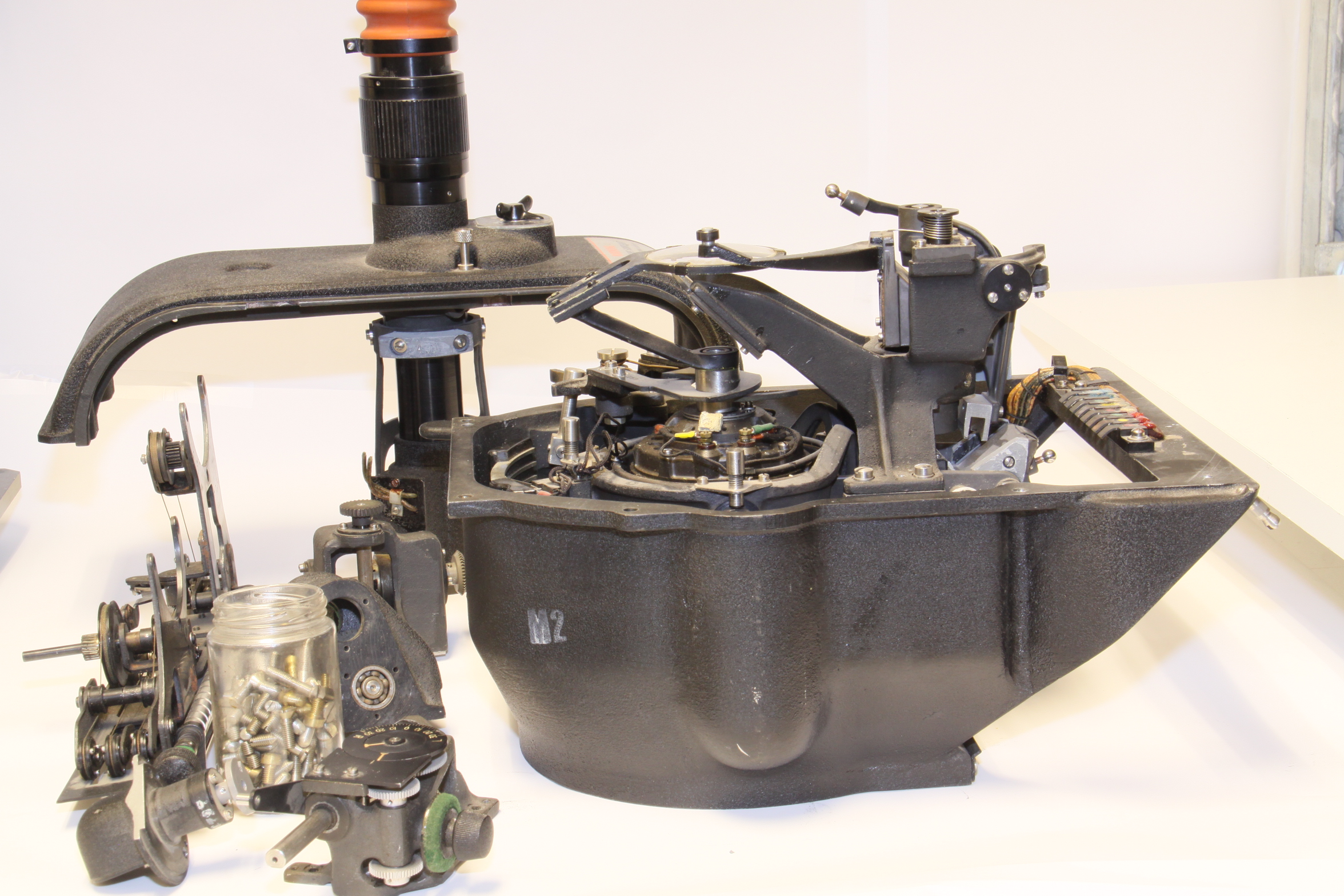
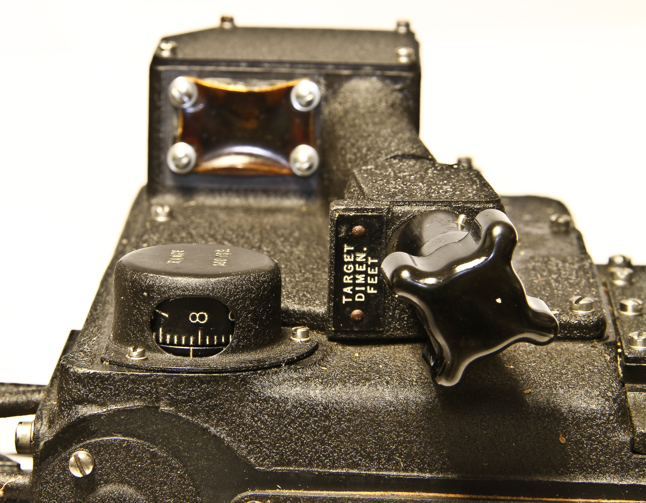
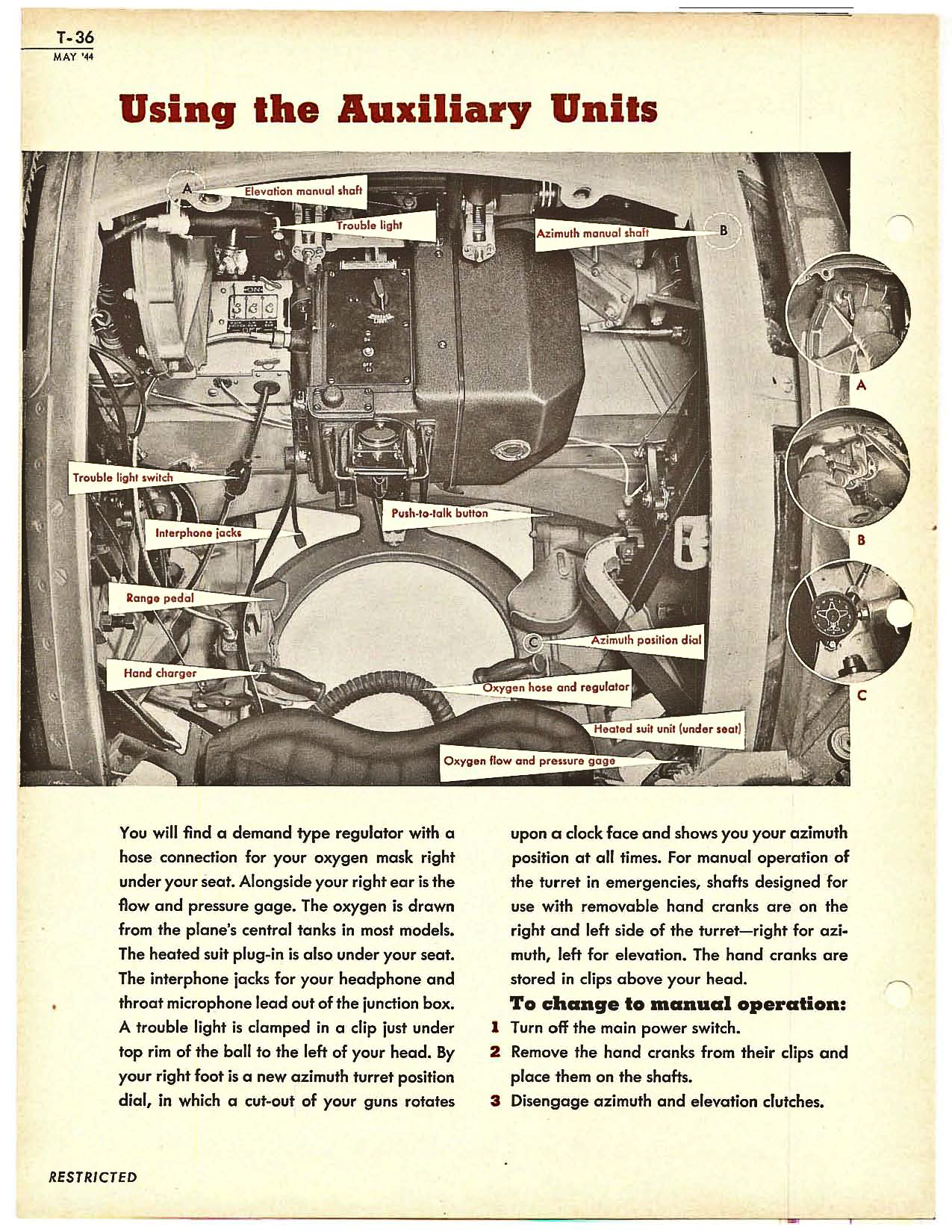
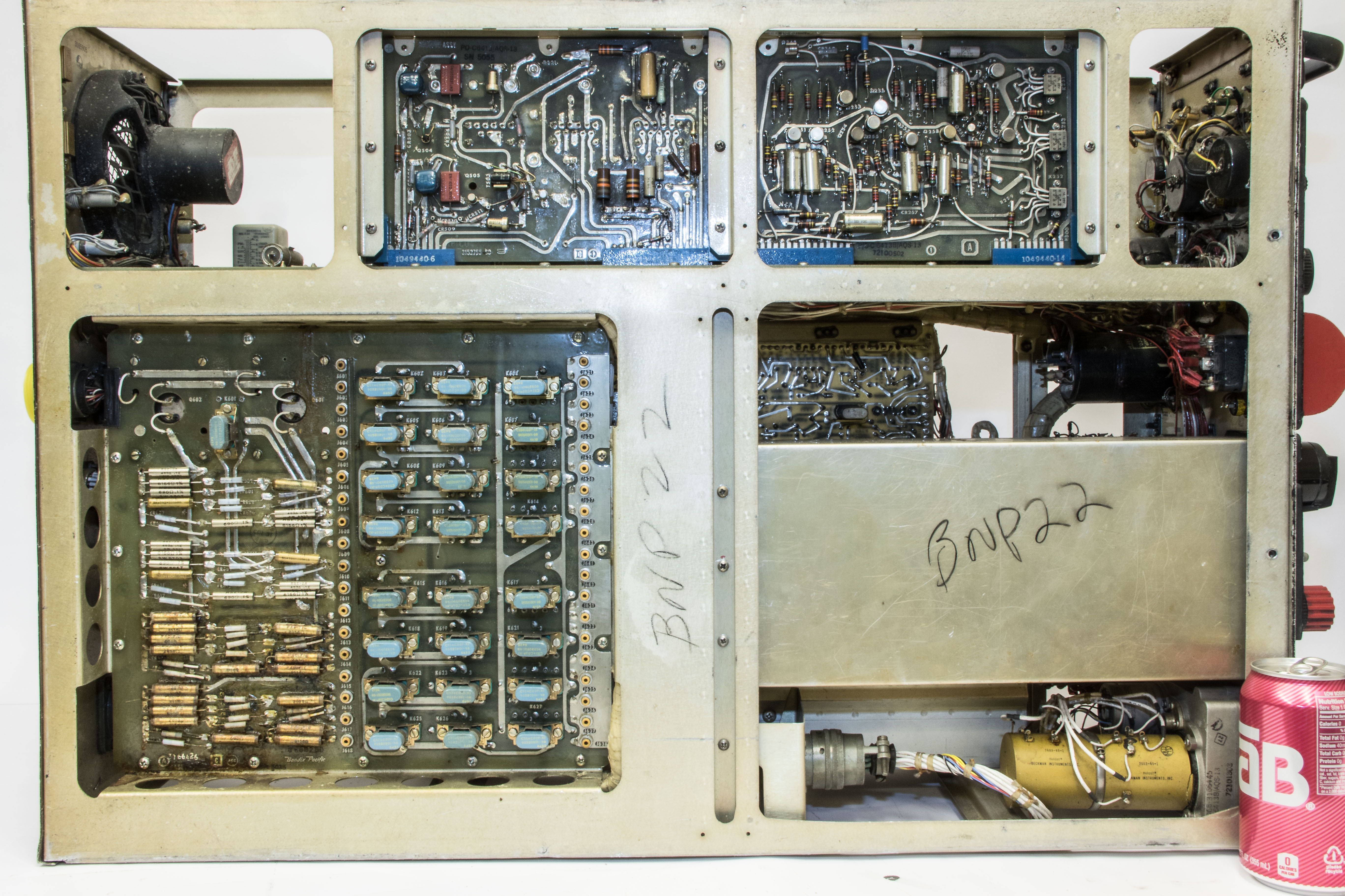
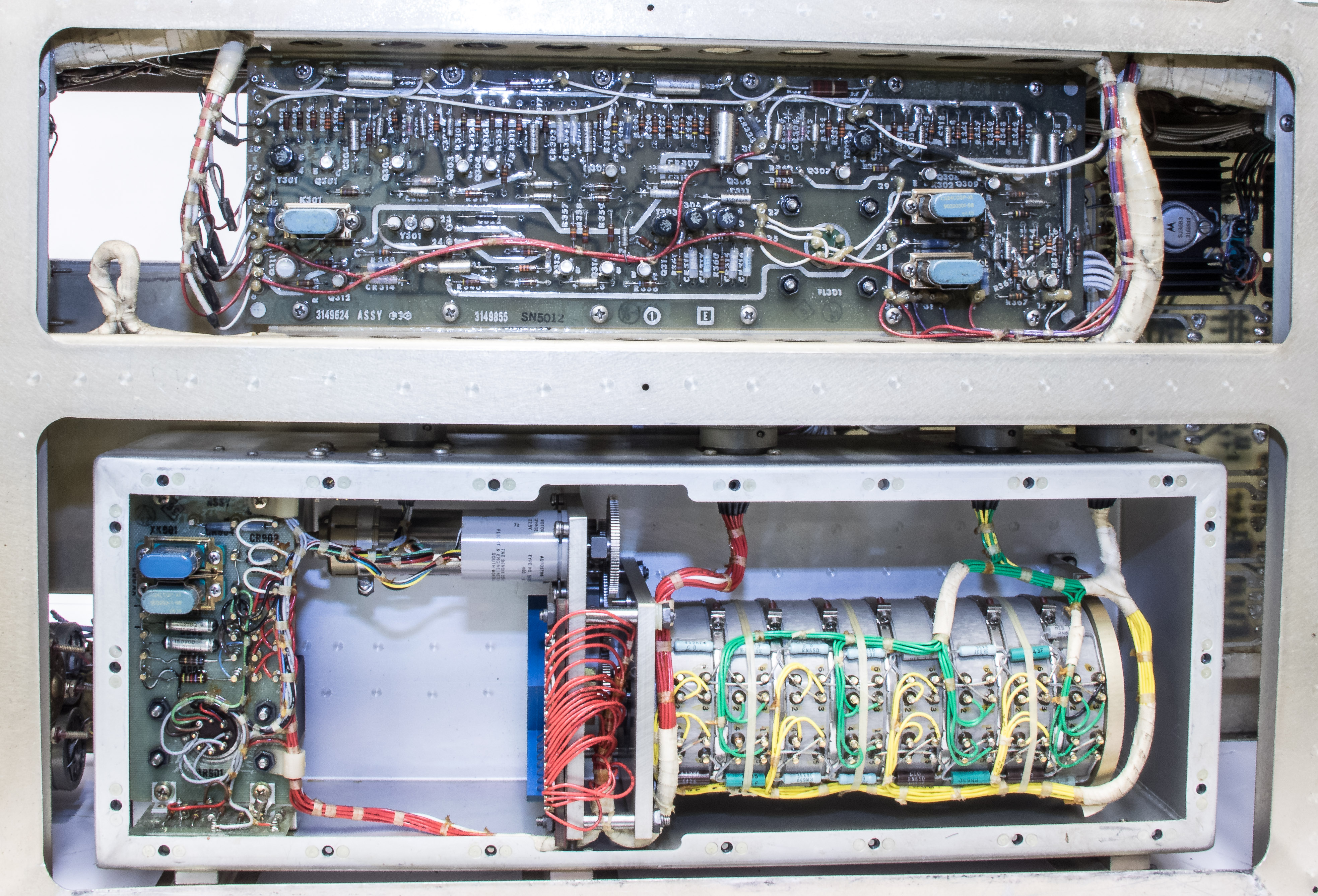
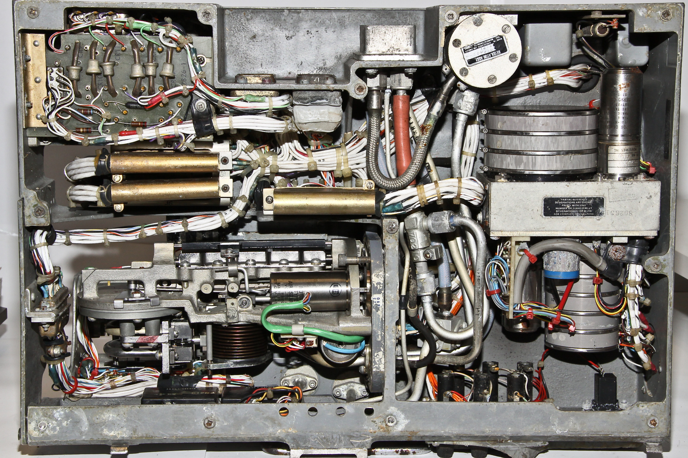
We are fortunate to have a complete Norden bombsight (with the optional X-1 reflex sight). A large part of the bombsight consists of two stabilization gyroscopes. The actual analog computing element (called the rate end) is the upper right portion. On the left is a diagram from the Bombardiers Information File (BIF), dated 1944 showing the major components. This very informative document is available from our site here. Below this diagram is is a closer view of the top portion. Using the knobs on the right side that connect into the rate end, the bombardier enters the altitude, airspeed, turn and drift rate of the plane, and the drag factor (“trail”) for the type of bomb to be dropped. Several other alignment controls must be set. The target is sighted through the telescope that looks down through the bombsight.
The rate end unit performs continuous calculations (as the sight angle to the target changes or new inputs are made) of when to release the bomb and the course the plane should fly. Near the end of the “bomb run”, the plane’s autopilot is connected to the bombsight and it actually steers the plane. The bomb release can be controlled directly by the computer.
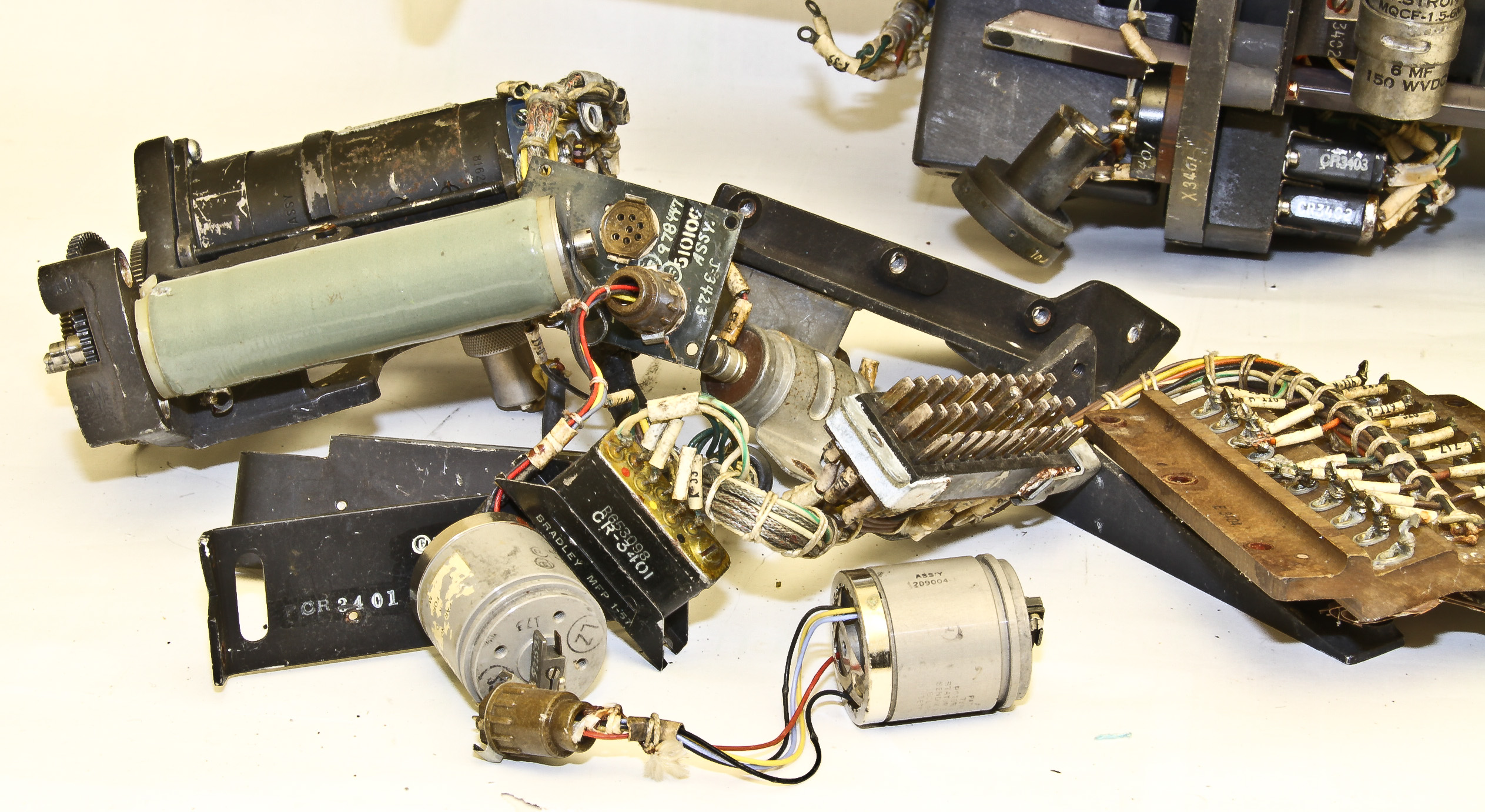
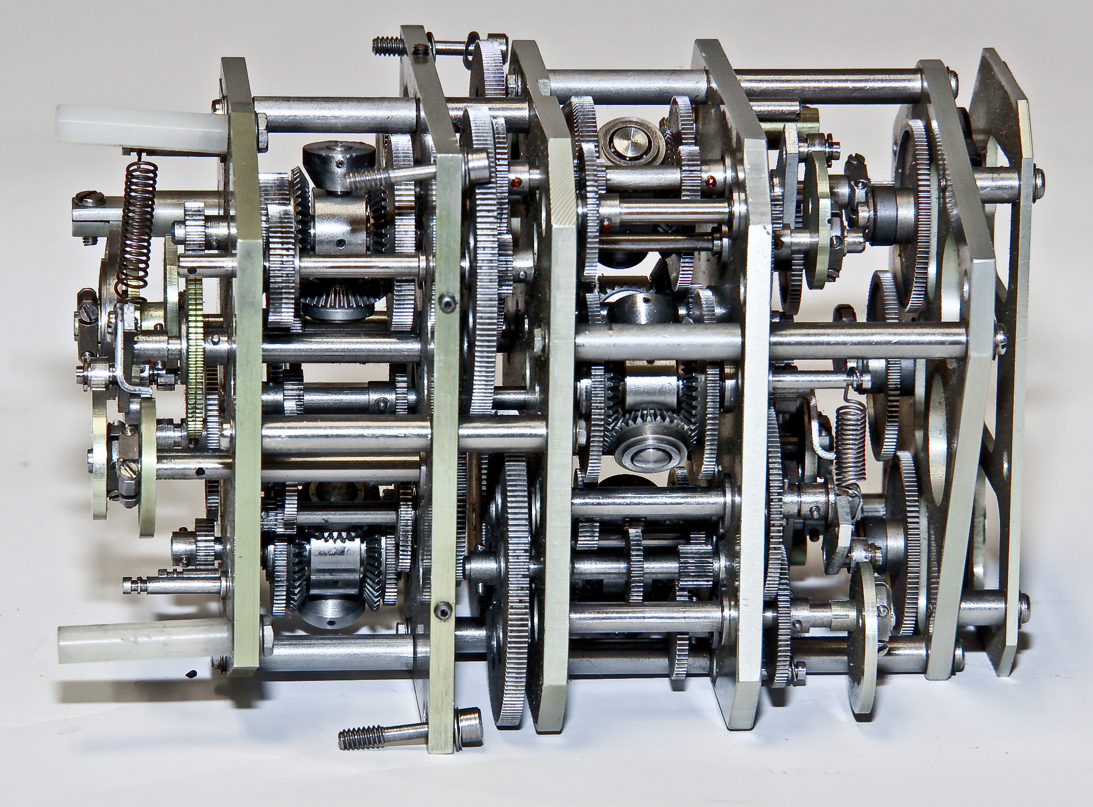
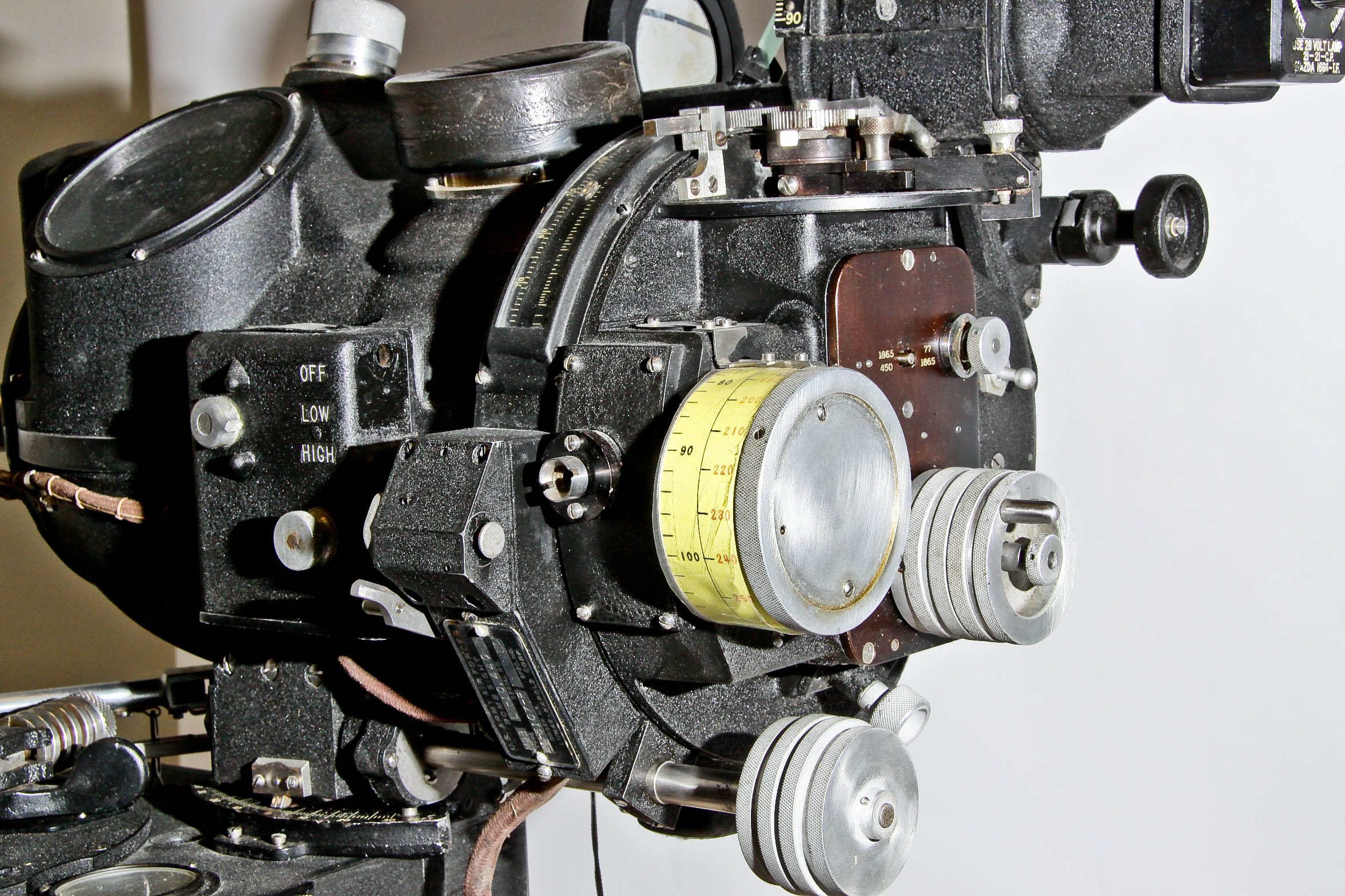
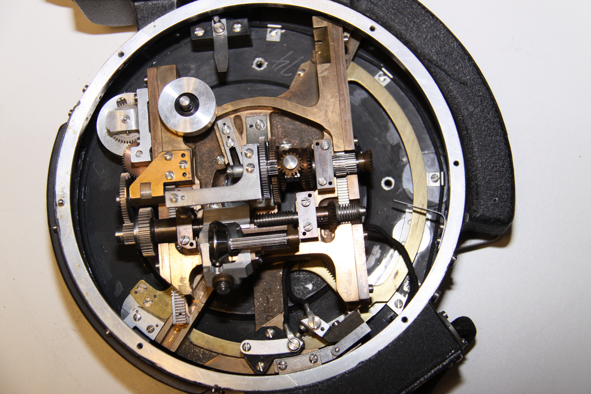
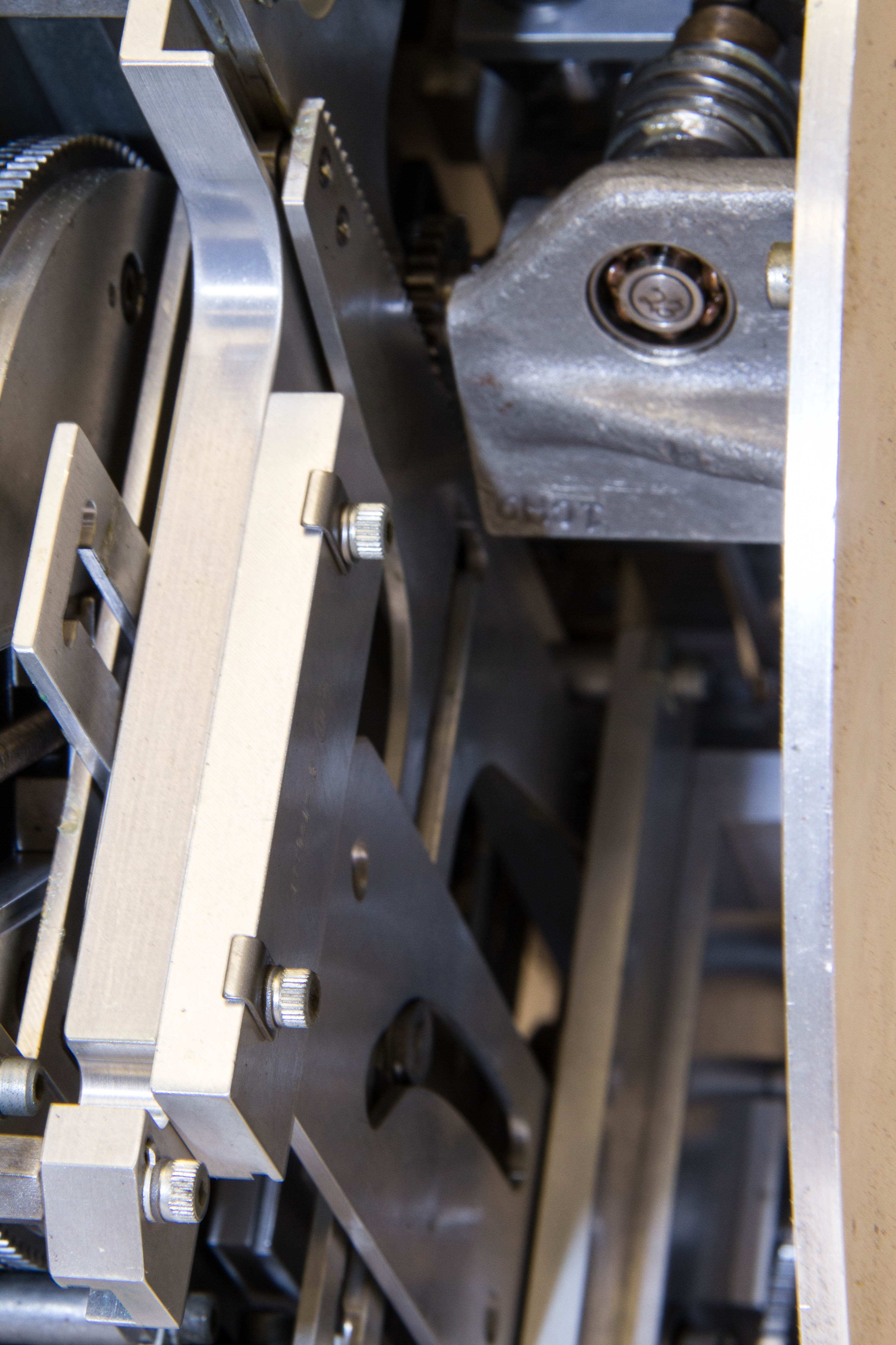
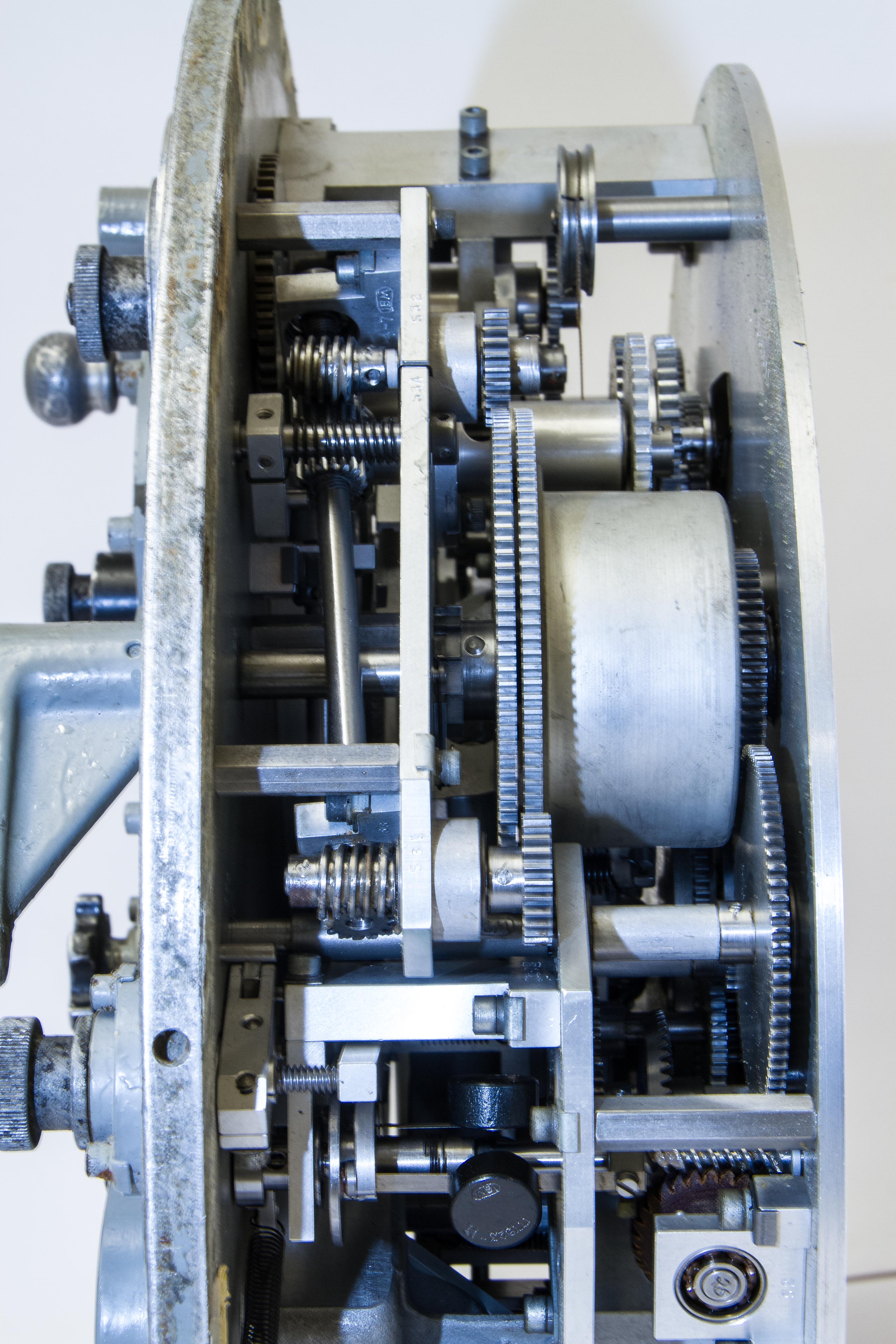
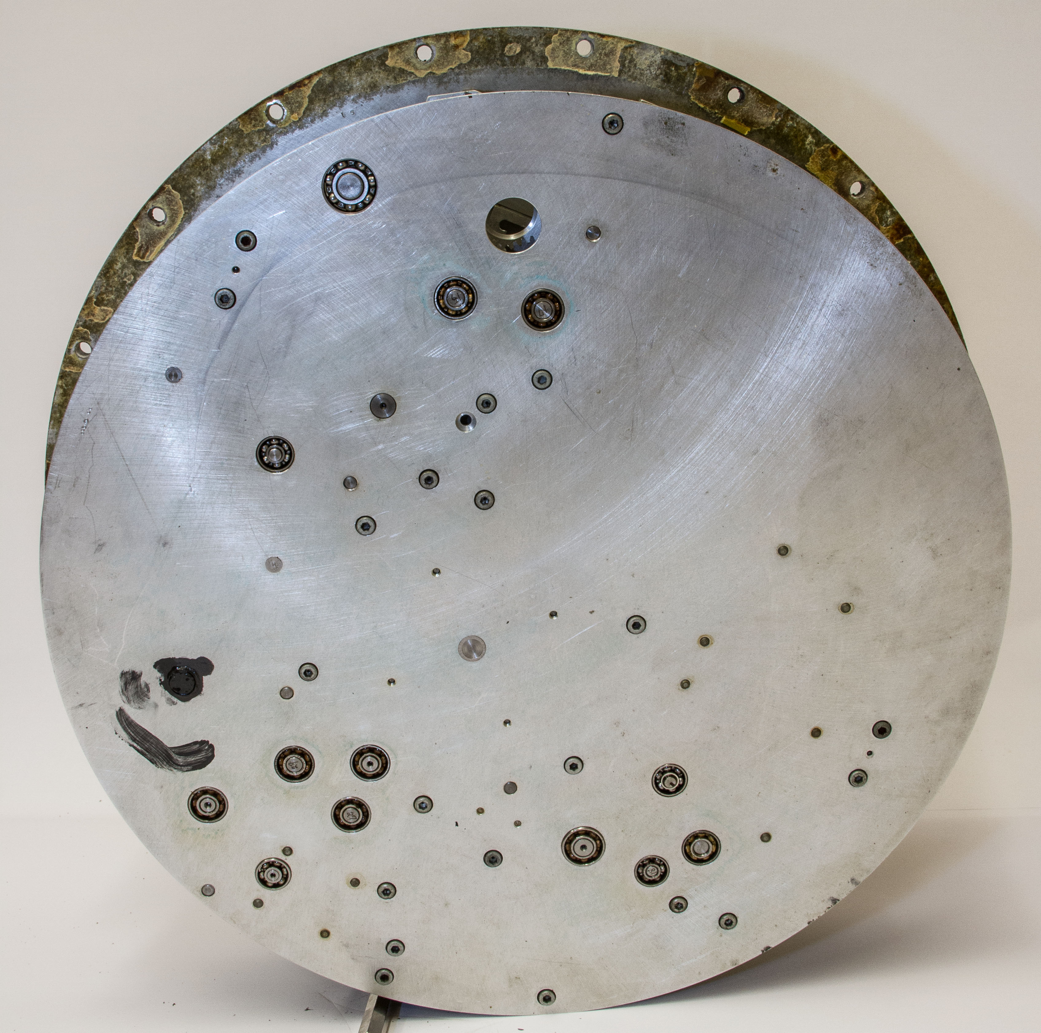
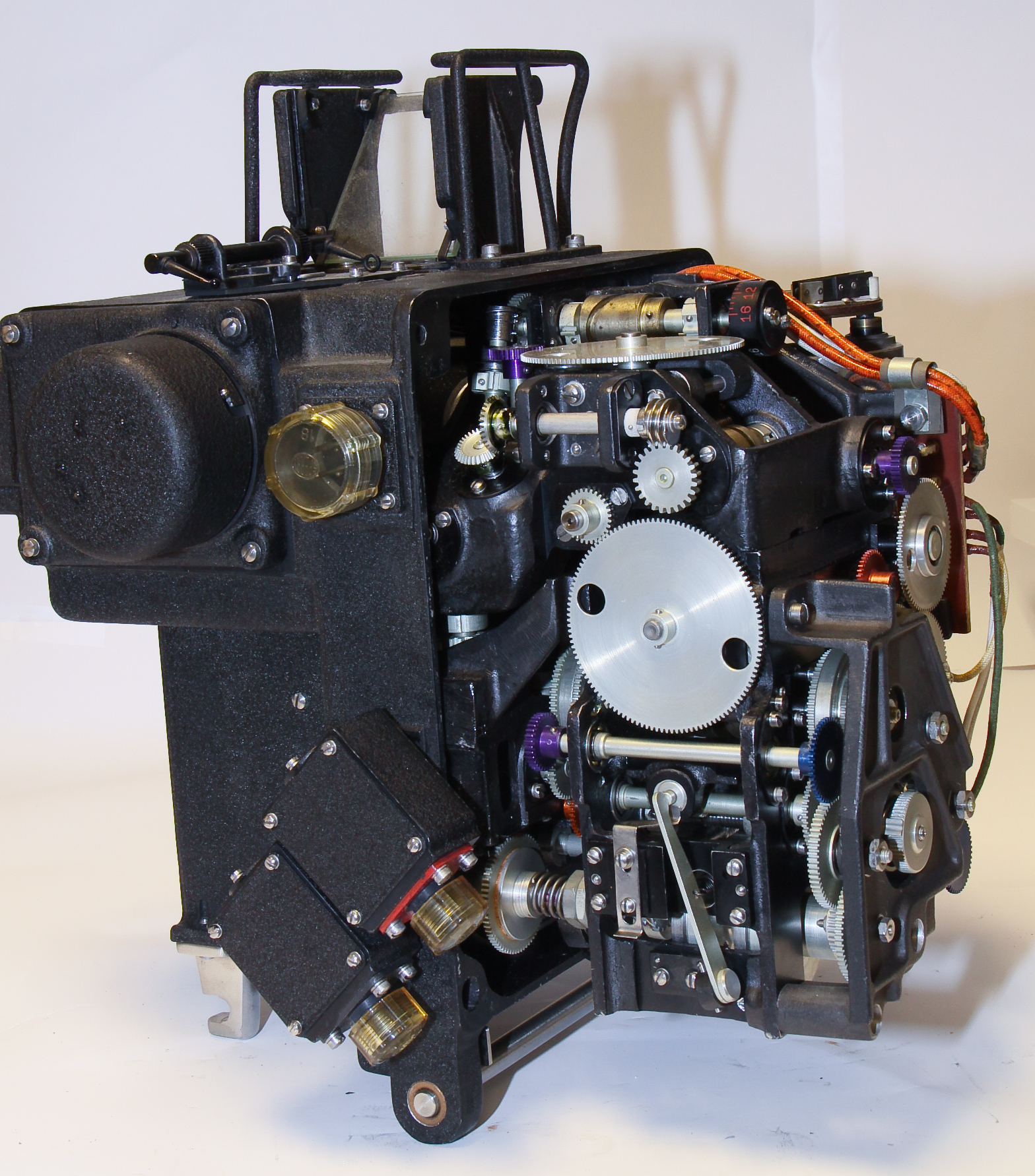
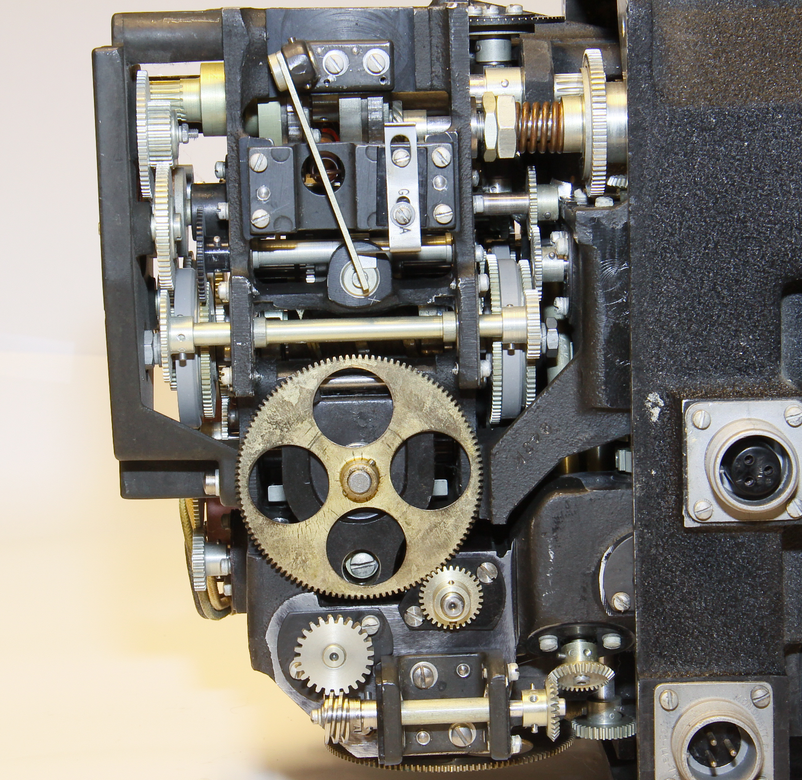
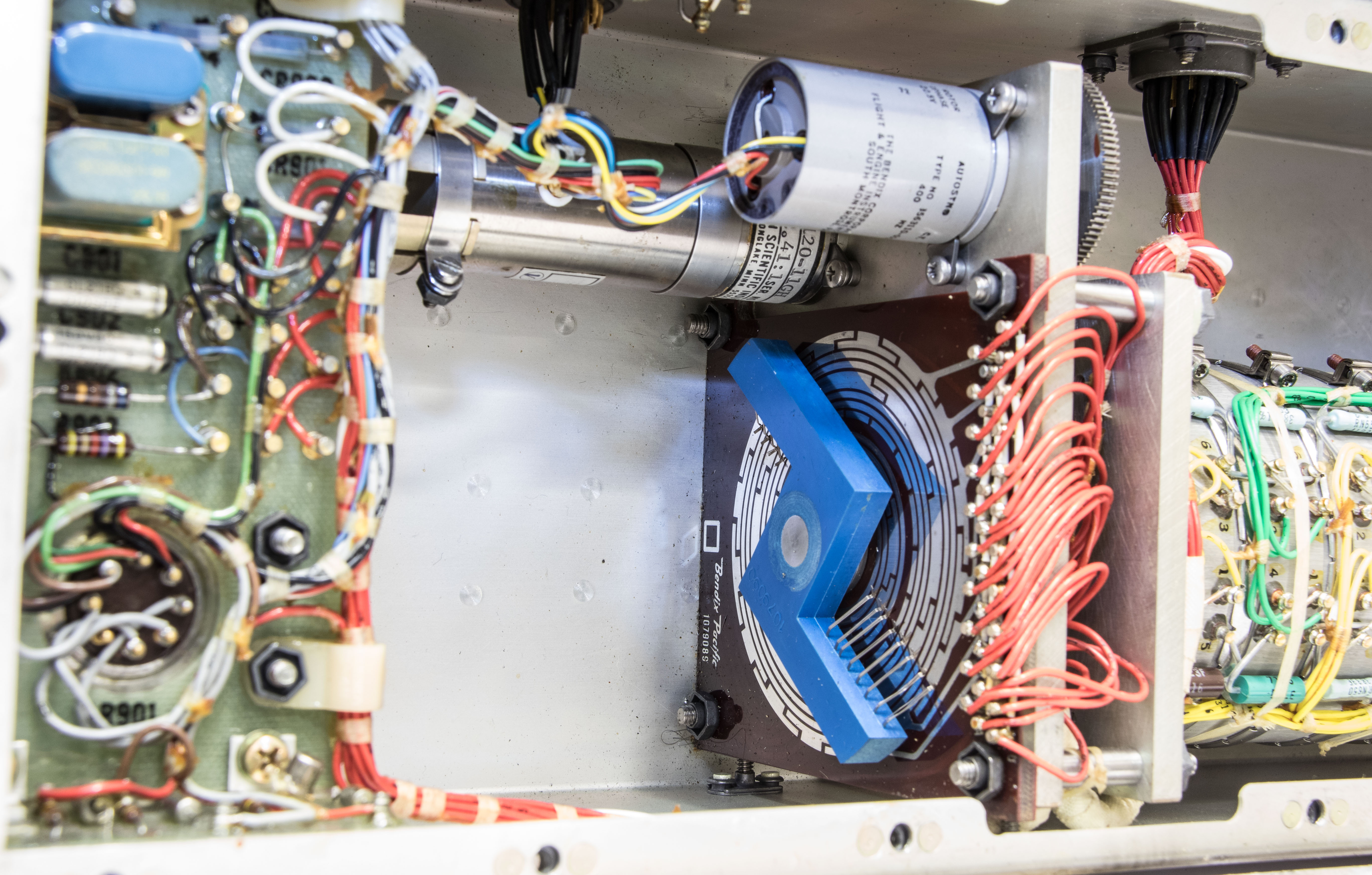
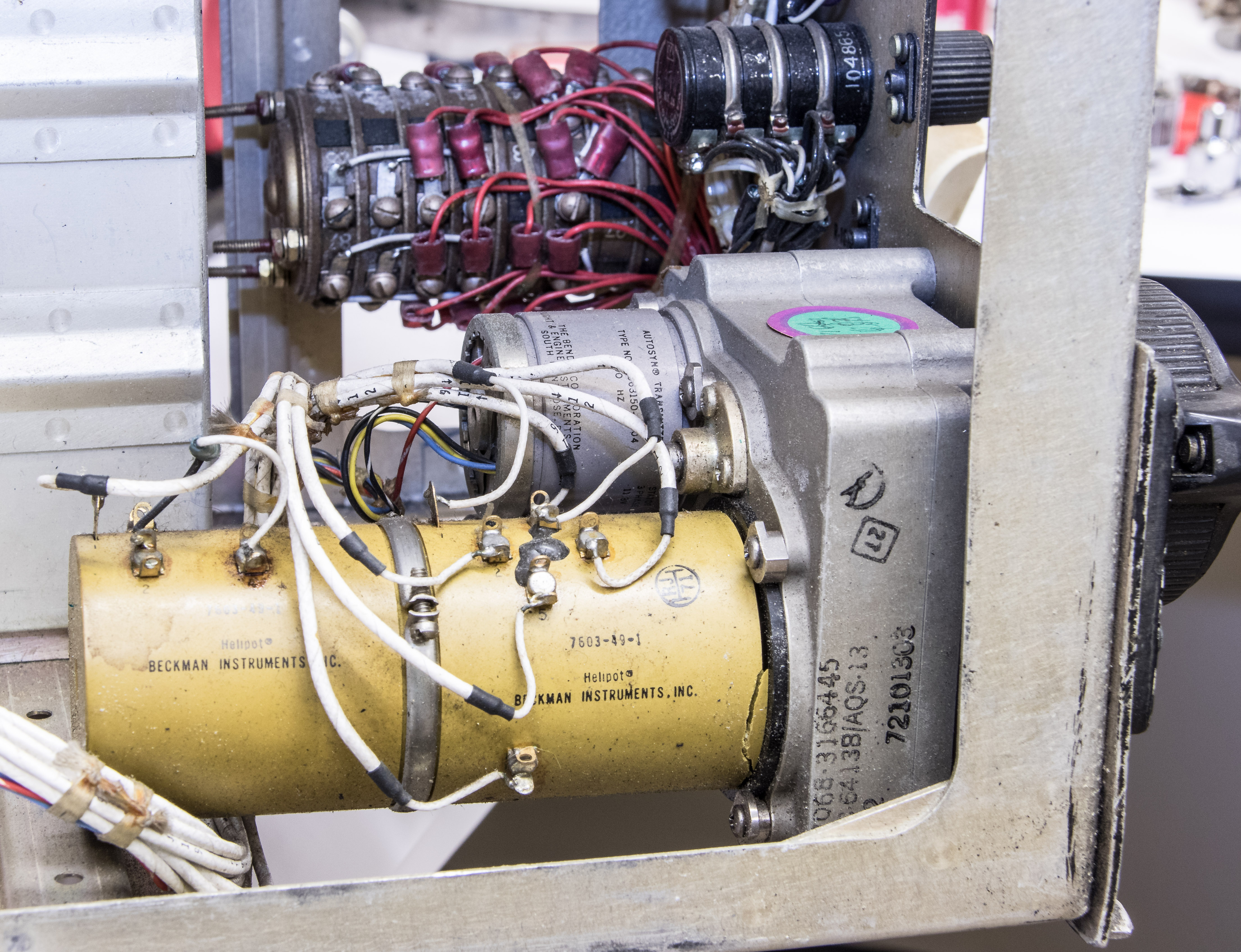
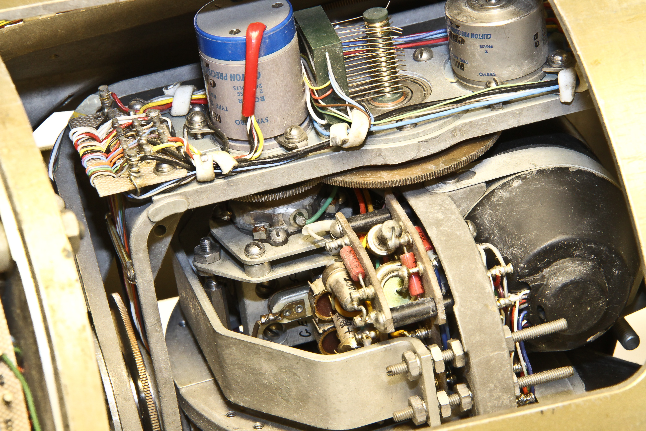
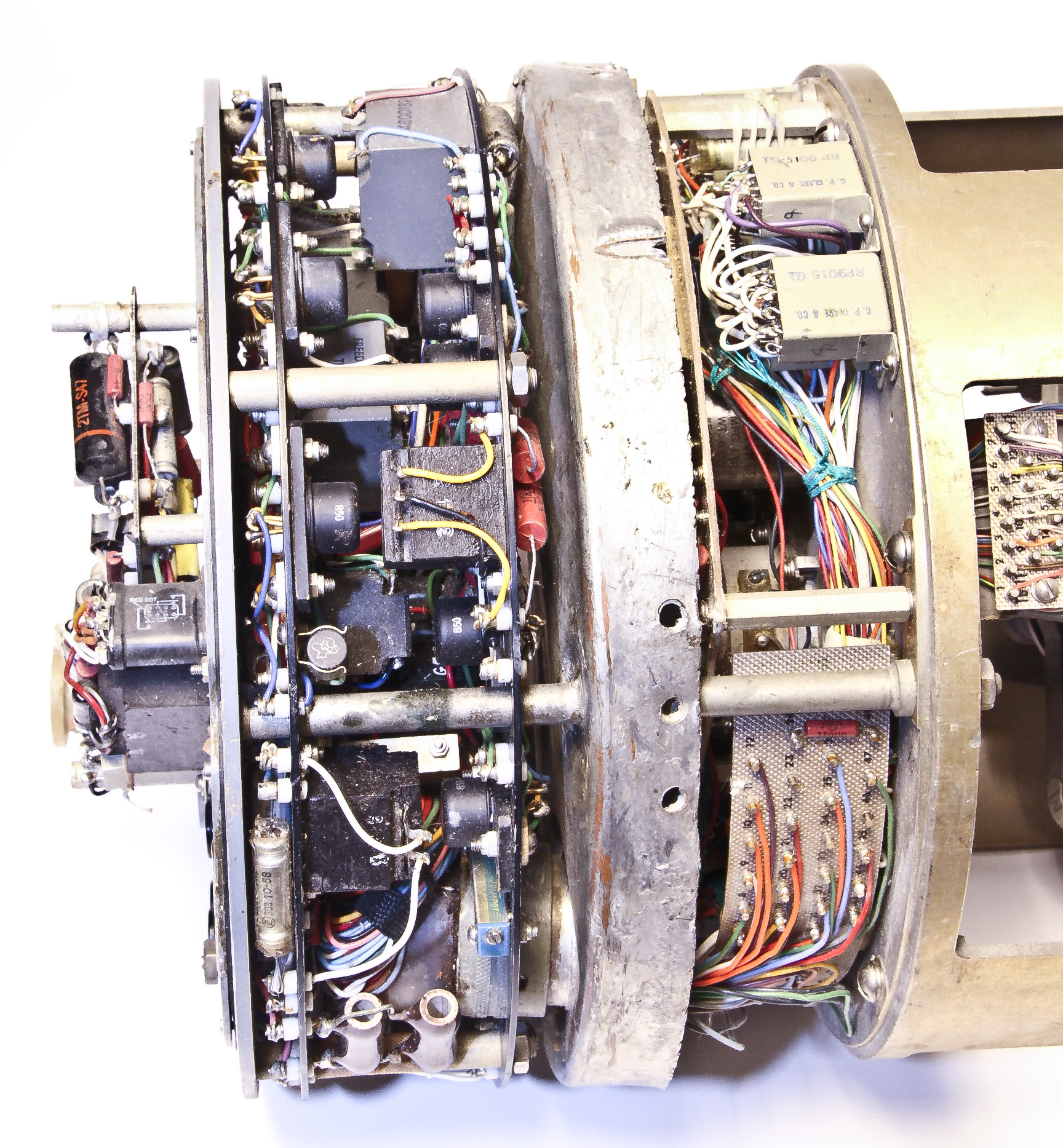
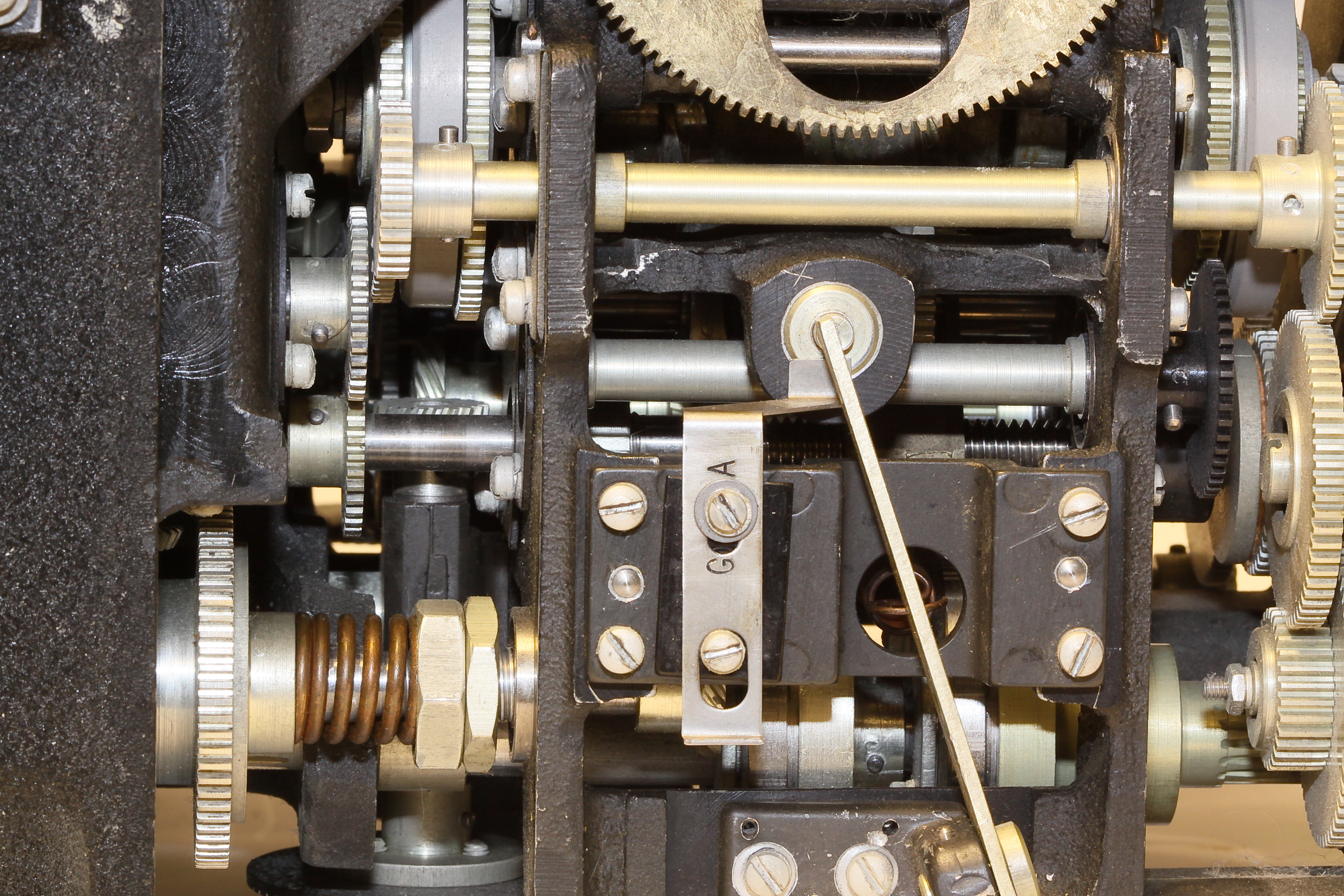
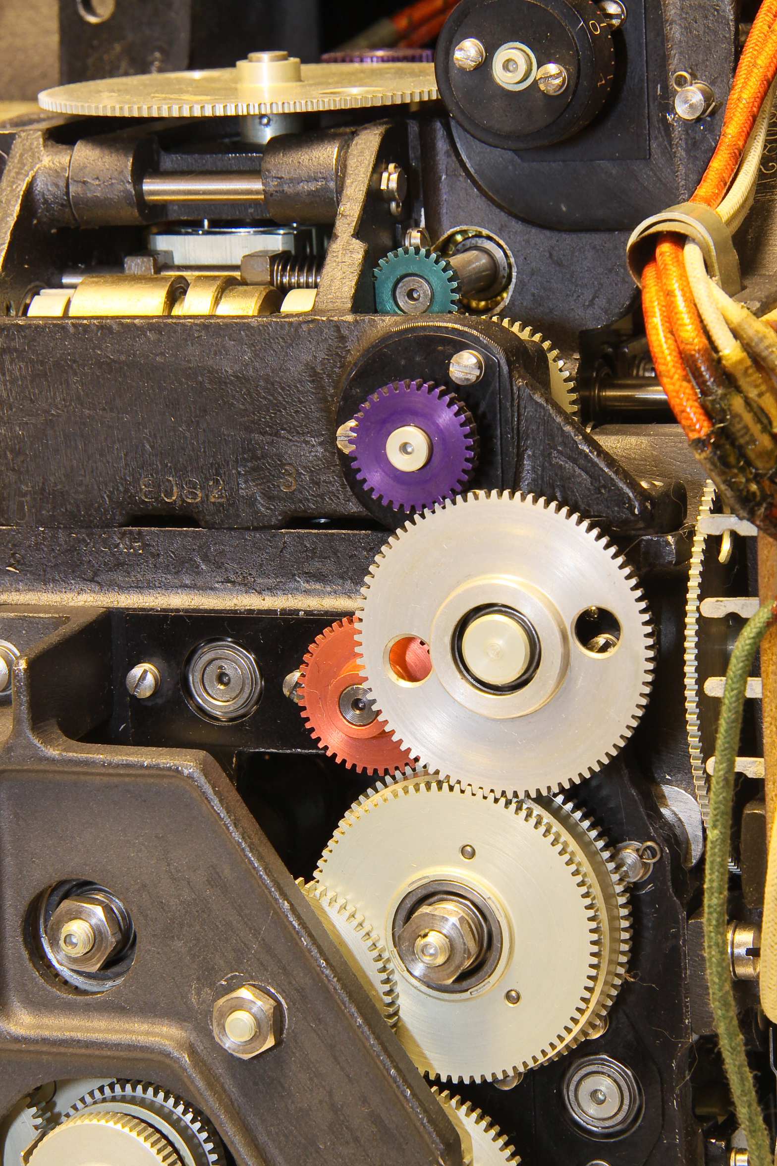
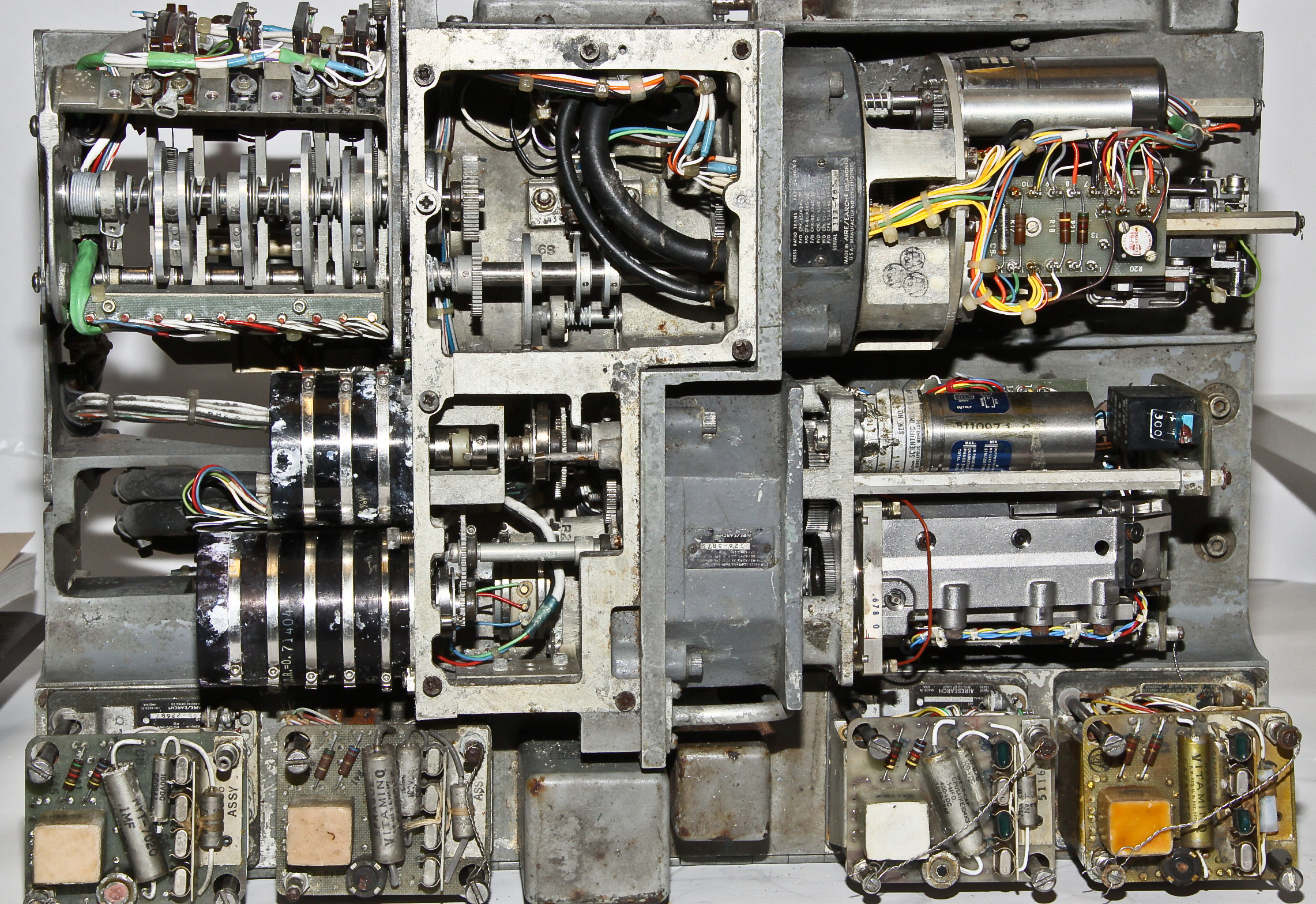
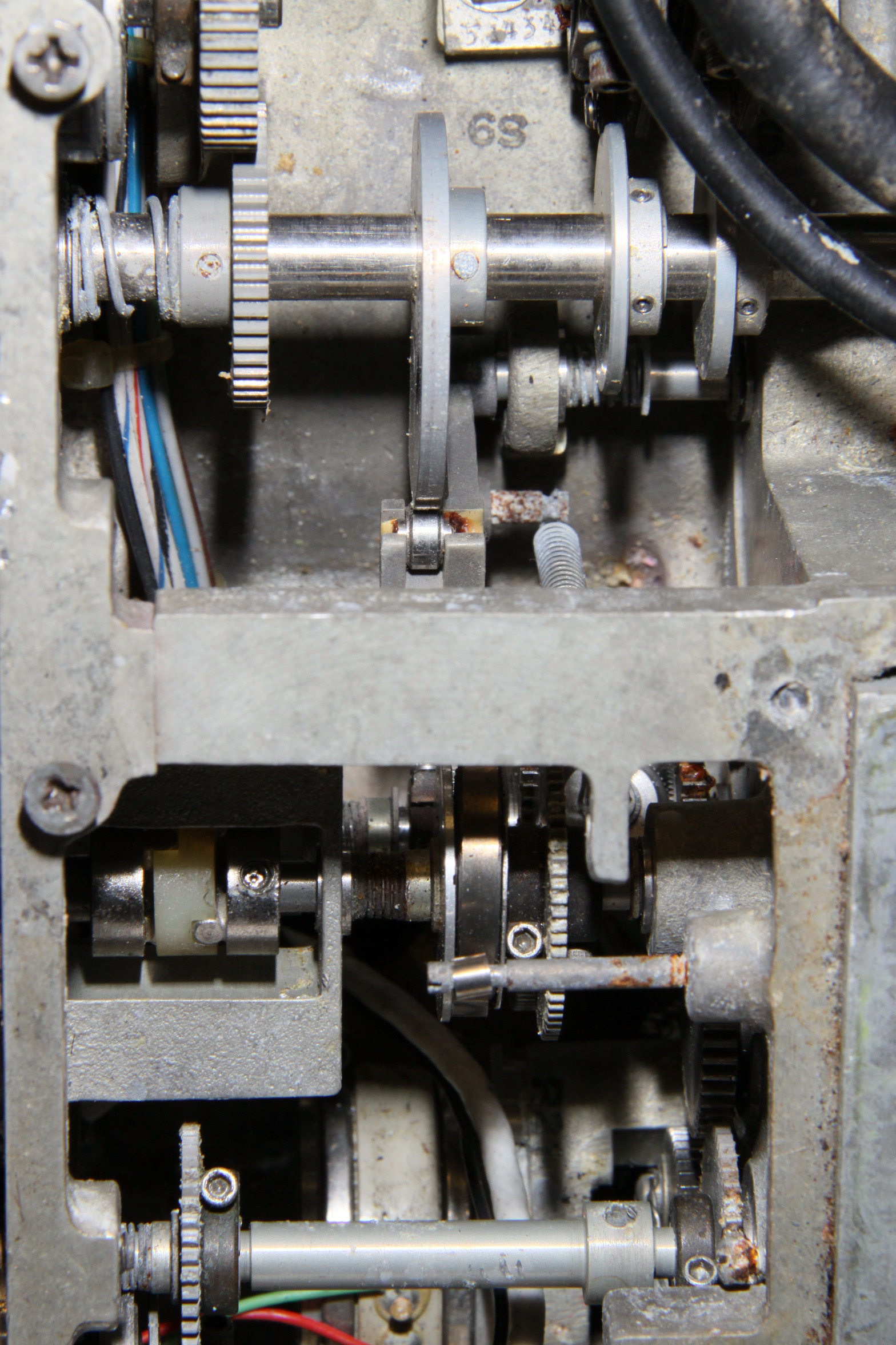
Fortunately, we also have a separate (and never used) rate end (the computer component). On the right it is taken apart so you can see the analog computing mechanism. Note the disk and wheel integrator assembly: the wheel is on a splined shaft just below the middle of the left half and the disk is sticking vertically out of the right half.
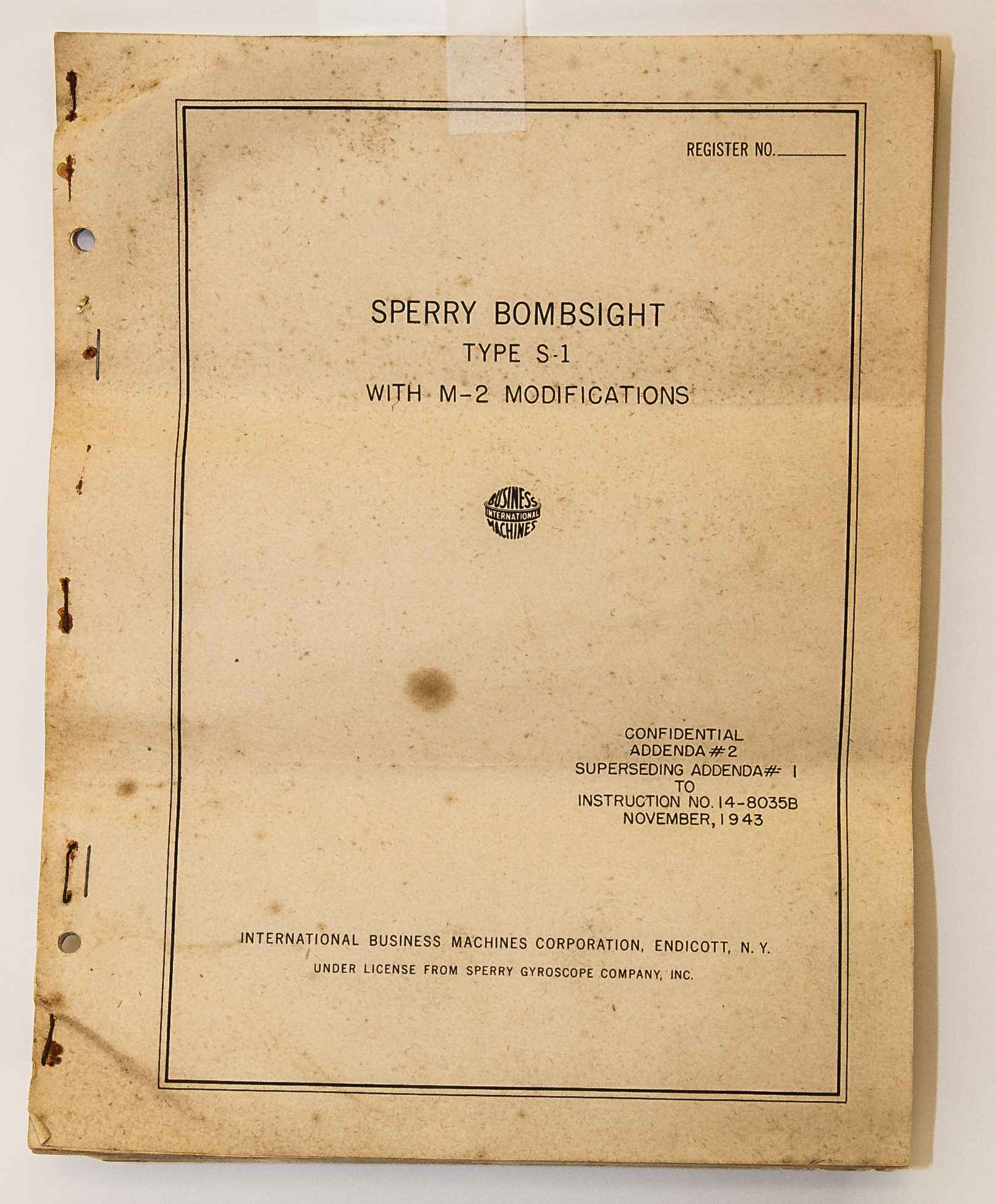
In addition to the bombsight, the BIF, and the extra rate end, we have the maintenance manual that which contains a wealth of detail on how the bombsight works.
World War II gave rise to some amazing electromechanical computers used by the military. The most impressive was the Navy's Mark I and Mark 1A fire control computers. used on battleships. A great reference to this device and many similar electromechanical fire control devices can be found at this site. Most of the complex fire control equipment, including the Mark I, was designed by the Ford Instrument Company (not associated with Ford Motors). Here is a great paper on Ford-designed mechanical analog computers.
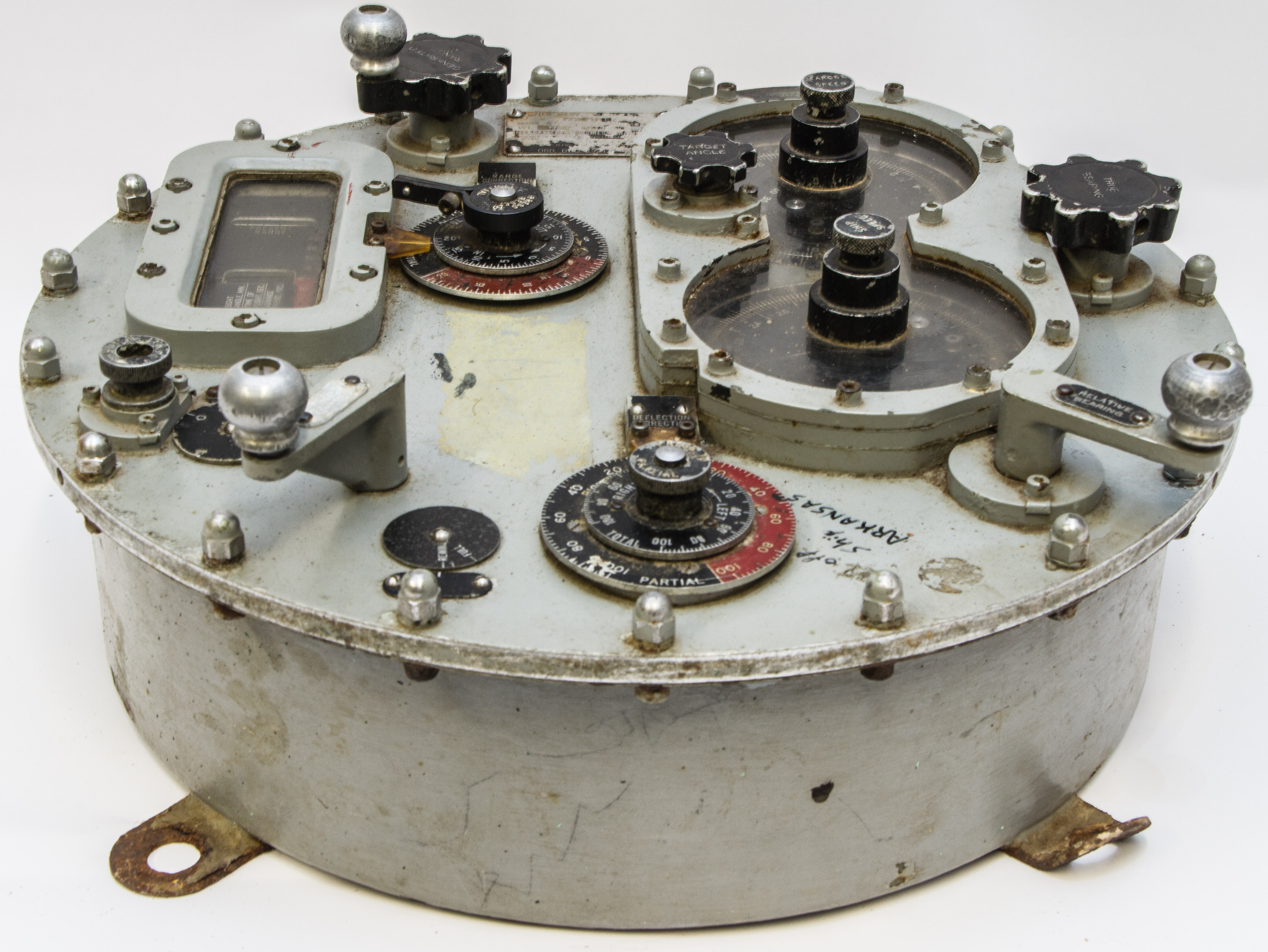
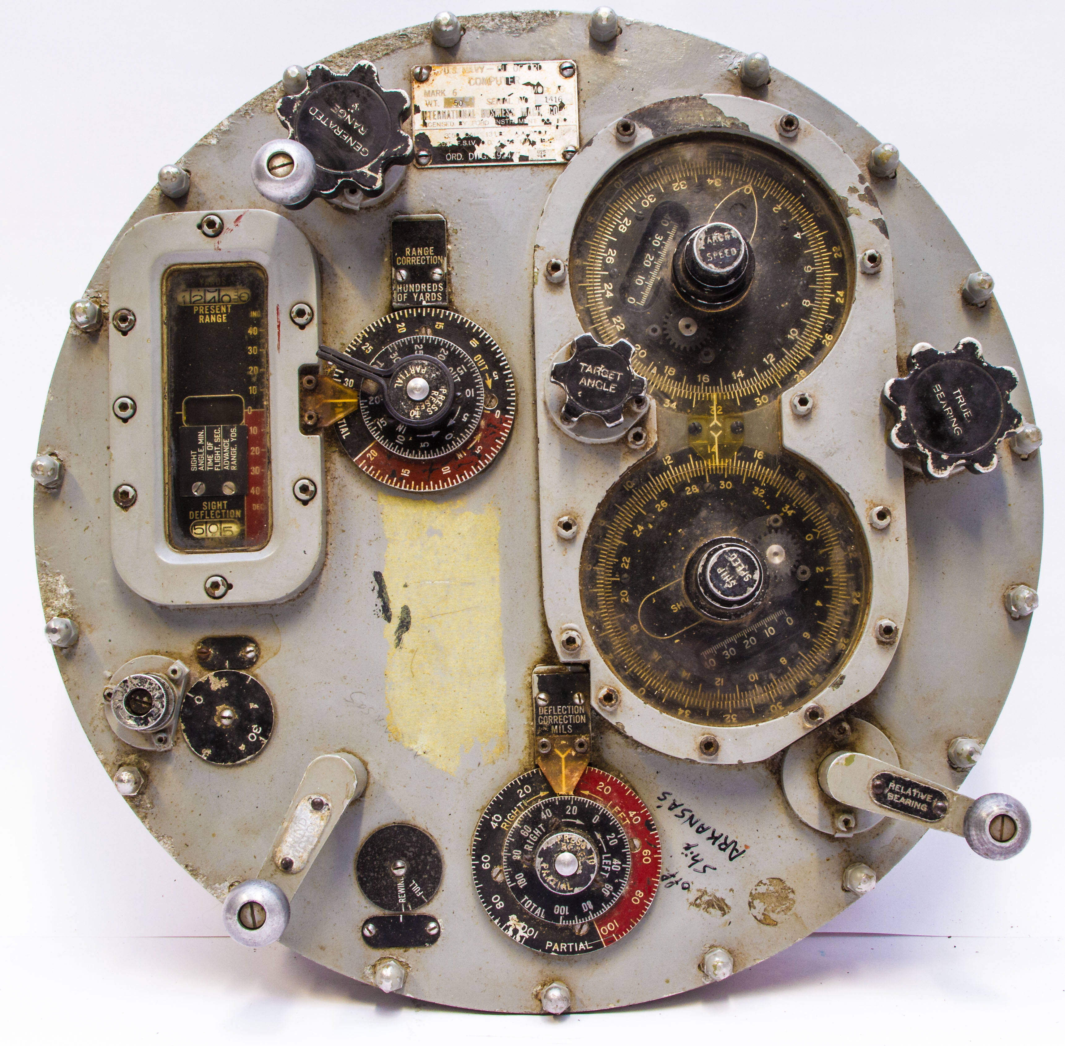
As far as I know, there are no intact versions of these large WWII devices outside of historic ships, although we have a couple of pieces of a Mark I in our museum. However, we do have a complete, but smaller, WWII fire control computer designed by the Ford Instrument company, and, interestingly, manufactured by IBM. It is mentioned in the above referenced paper, we find "Ford's answer to the merchant ship problem was the Computer Mark 6... Although only about the size of a large wheel of cheese, it ingeniously contained a simplified capability for solving the surface fire control problem."
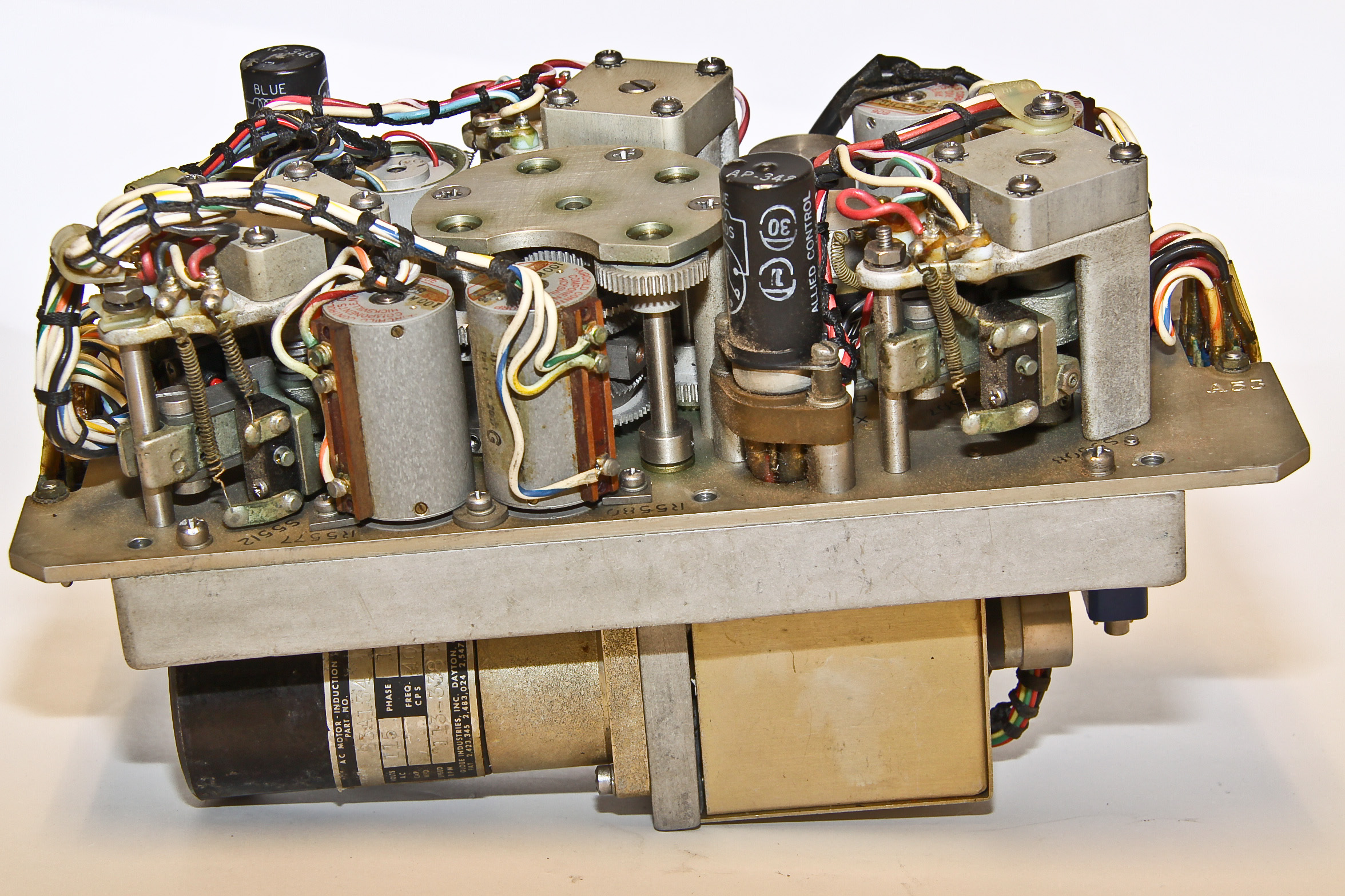
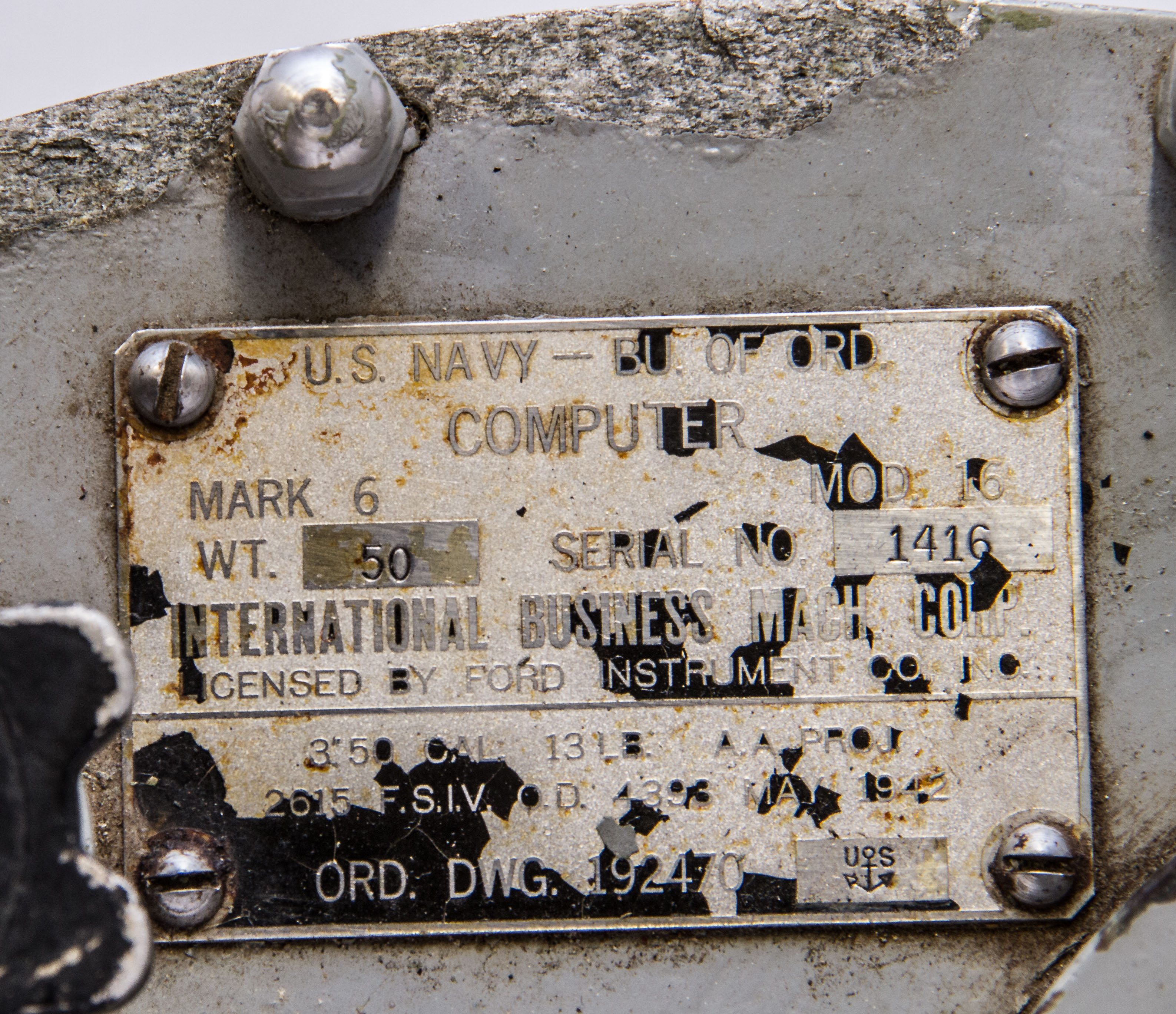
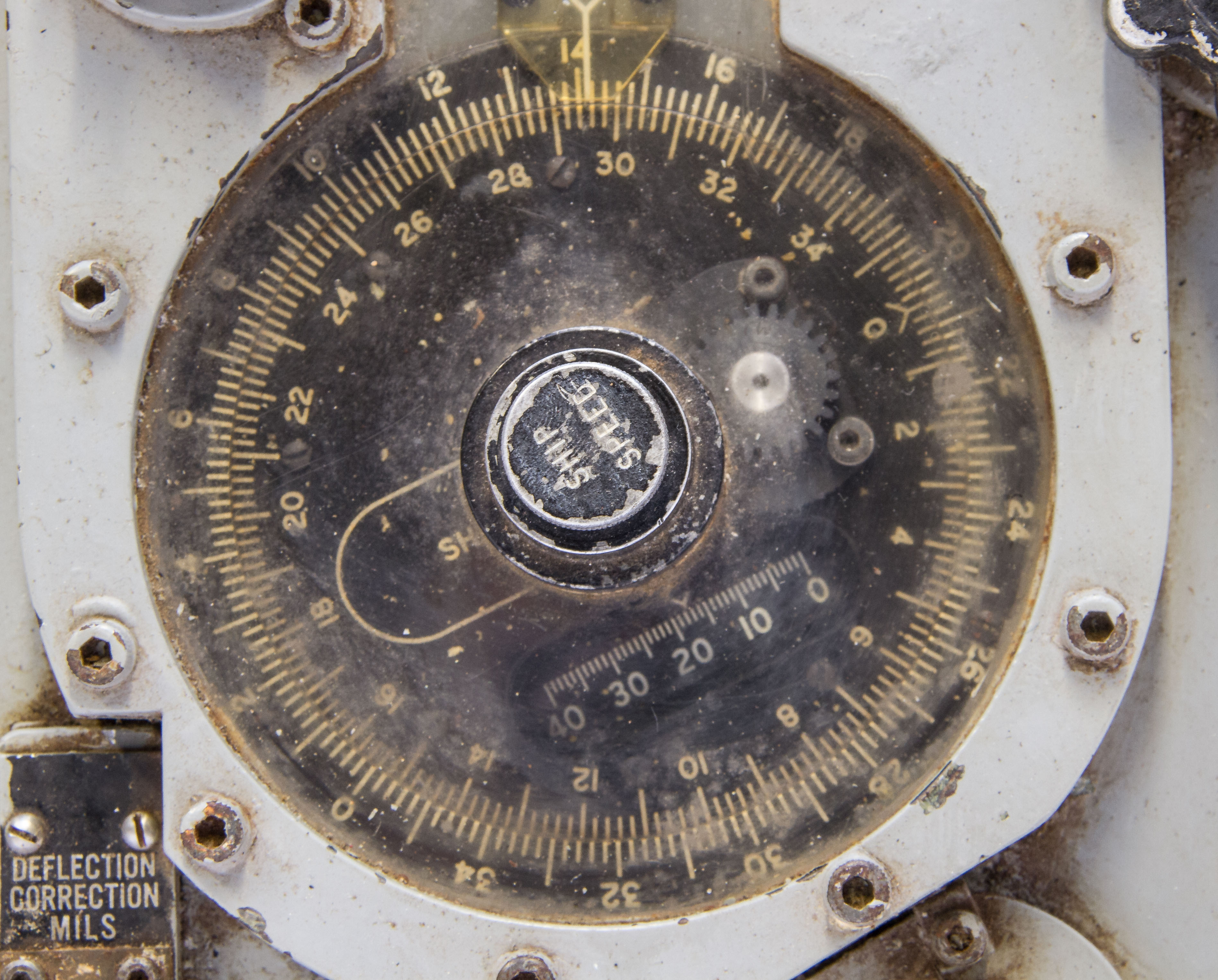
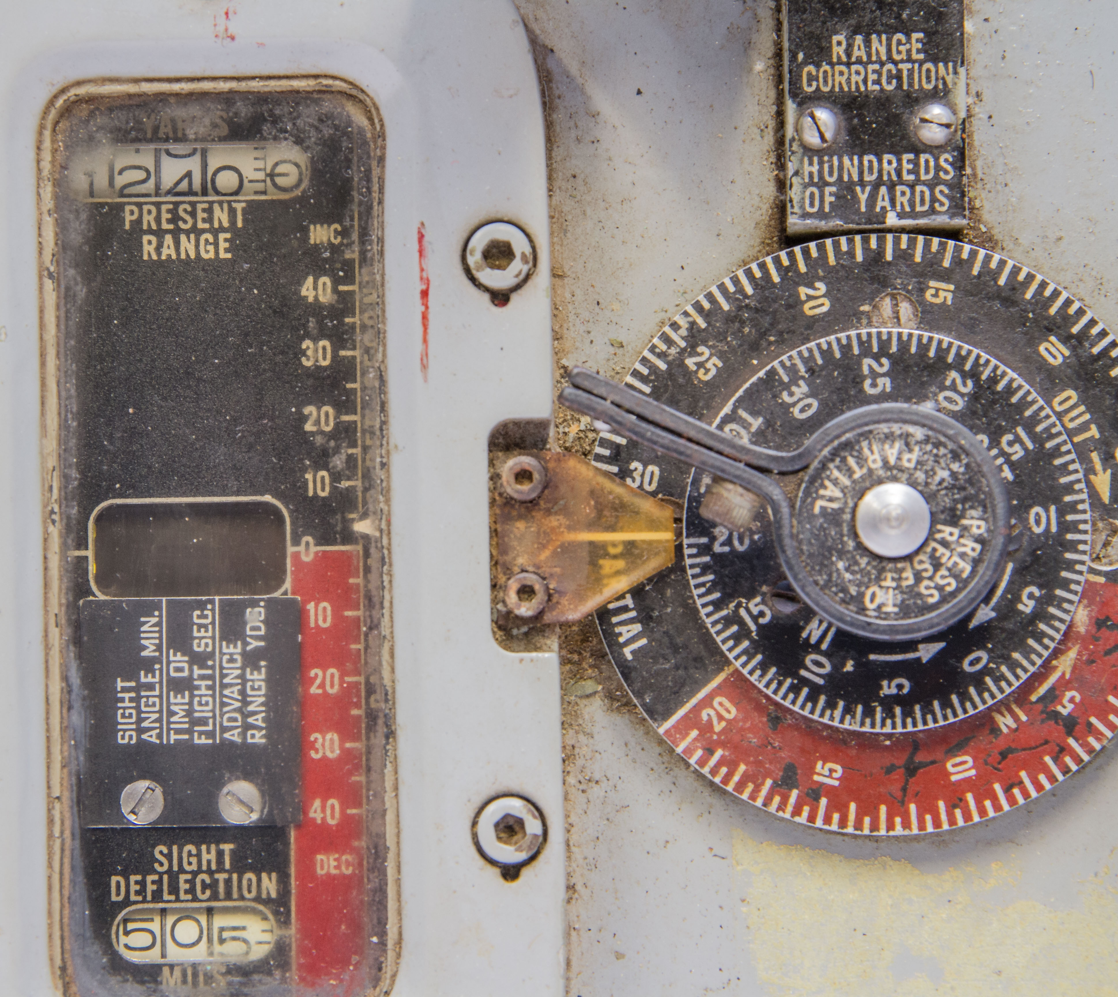
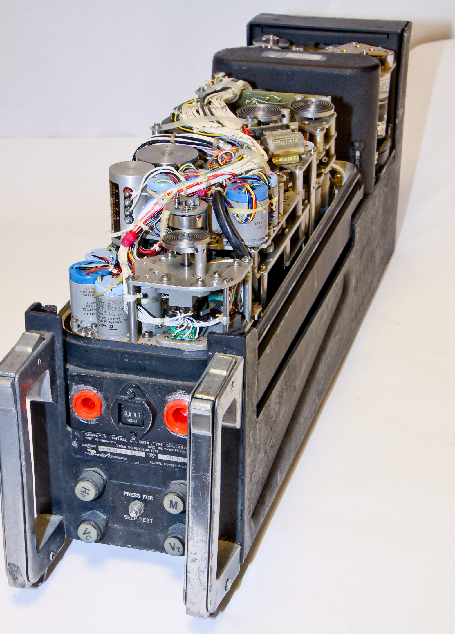
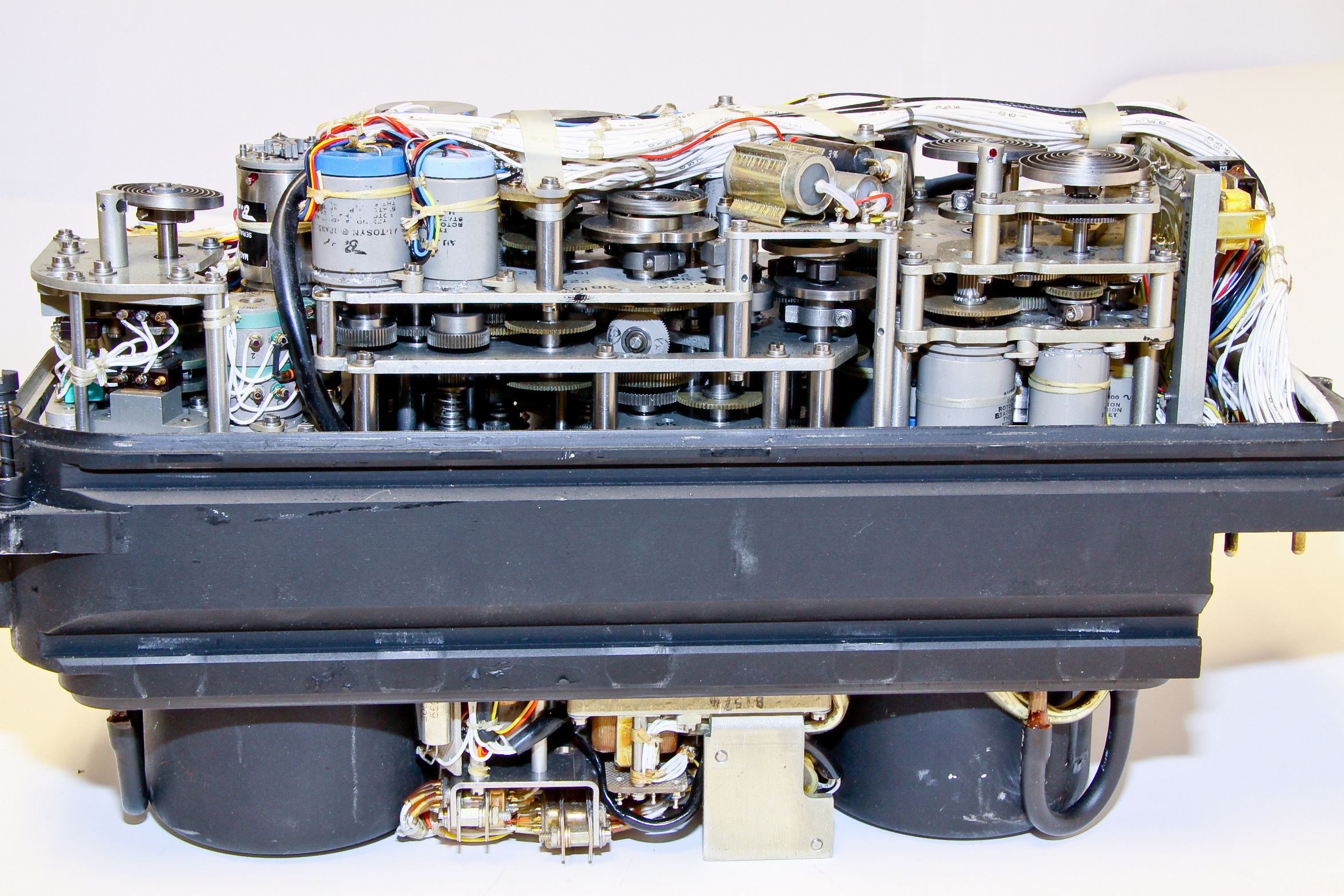
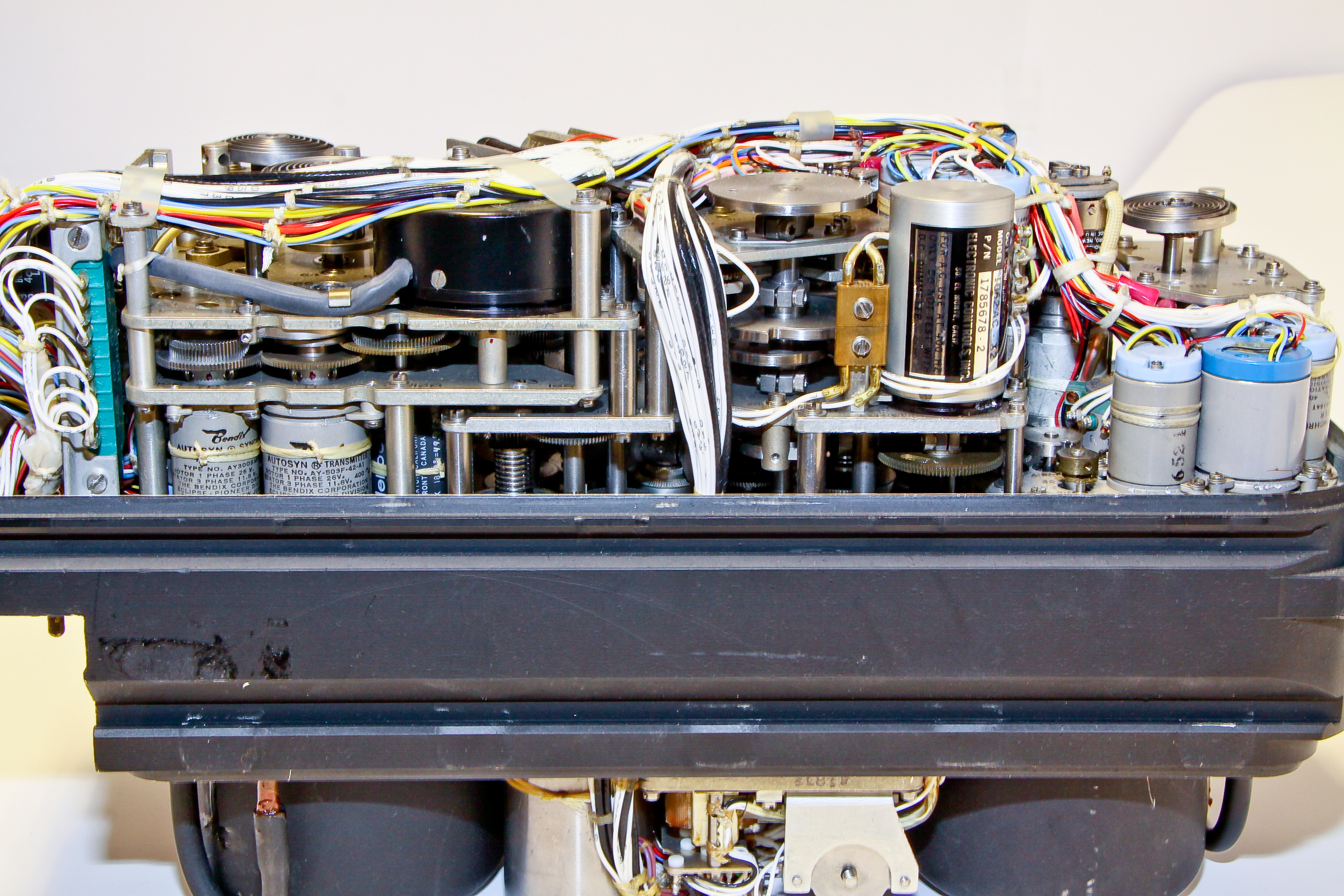
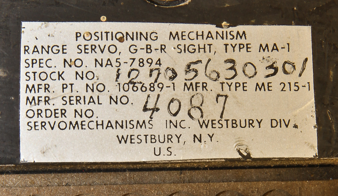
Figures 1 and 2 shows our "large wheel of cheese" sized Mark 6 mod 16 computer. Figure 3 shows a close up (hard to read, I recommend the largest size photo) of its label showing its pedigreed (Ford and IBM) along with a May 1942 date. The label notes that it is for a 3" 50-caliber gun shooting a 13 lb. AA projectile. Other WWII naval fire control computers were electrically powered; the Mark 6, however, is manually powered using a spring motor, wound by hand with the knob on the lower left of Figure 2.
I can find only three references to this device after significant searching: (1) the above mentioned paper on Ford computers, (2) Figure 9, a picture of the device in a restored WWII destroyer escort, and (3) Figure 16, a picture in a navy manual describing fire control equipment in a 16" gun turret.
(Both these sites are great if you are interested in navy ships, especially from WWII.)
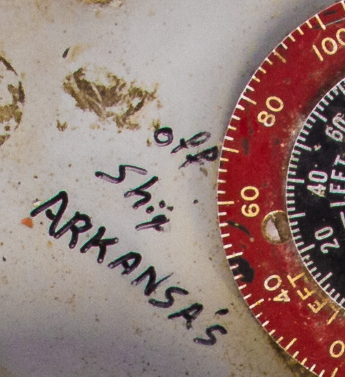
There are several mysteries here. First, even though the Ford computer reference above talks about defensively equipped merchant ships, Figure 6 shows that someone wrote "off ship Arkansa's" [sic] on our device. That seems to be a reference to an old WWII battleship, the USS Arkansas, BB-33, which, in fact, did have 3"/50 guns. In addition, we have the Figure 9 picture of our computer mounted in a destroyer escort. Since the 3"/50 gun was used on almost every US ship in WWII, it is likely that the Mark 6 computer was used on many ships. And, we have what must be a variant model associated with the main guns of a a battleship (Figure 9). The second mystery is the fact that the label mentions an "AA projectile", yet the details of the Mark 6 operation seem to be suited to ship-to-ship firing. Also, the above Ford reference talks about "surface fire control" for the Mark 6.
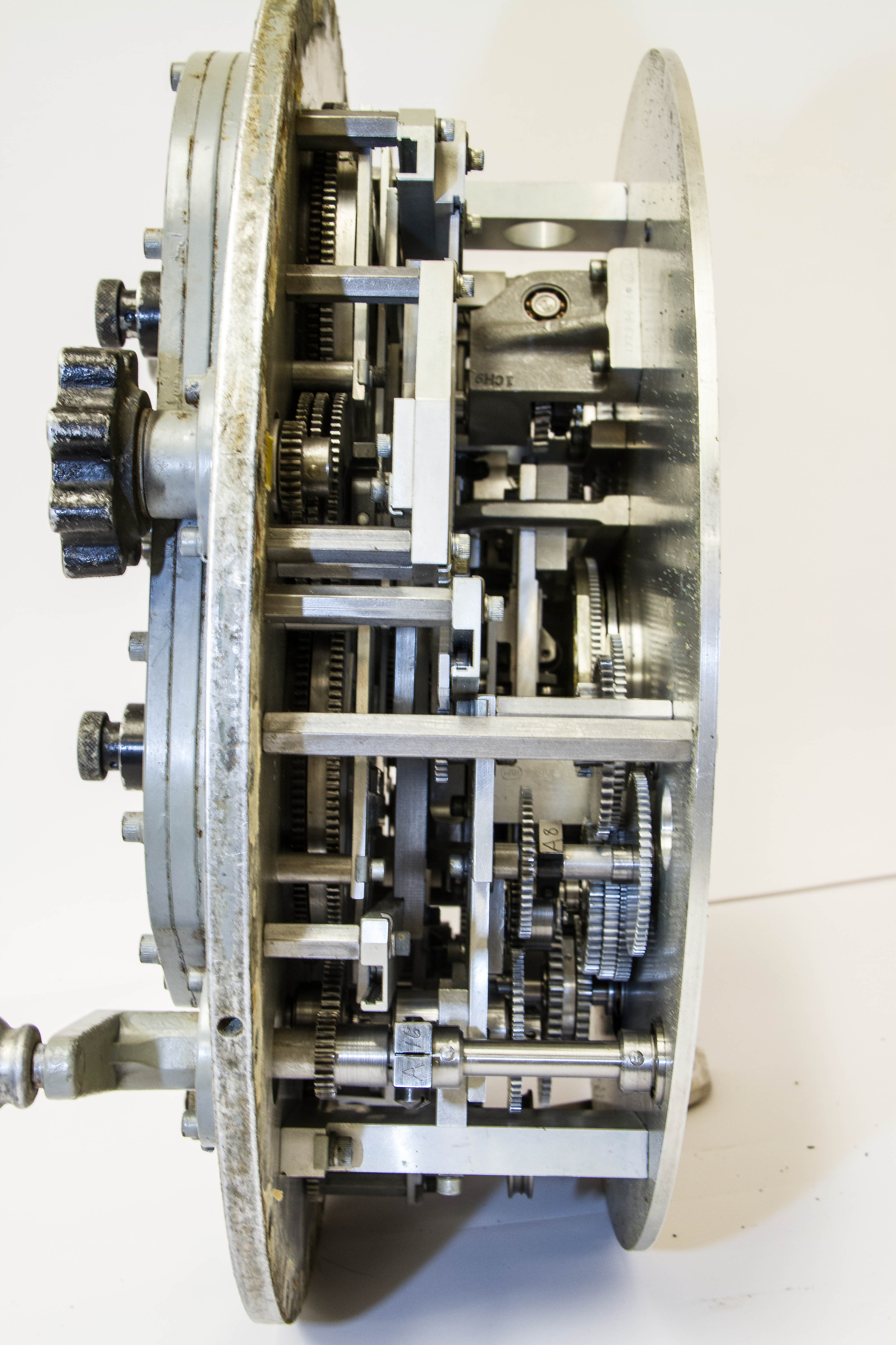
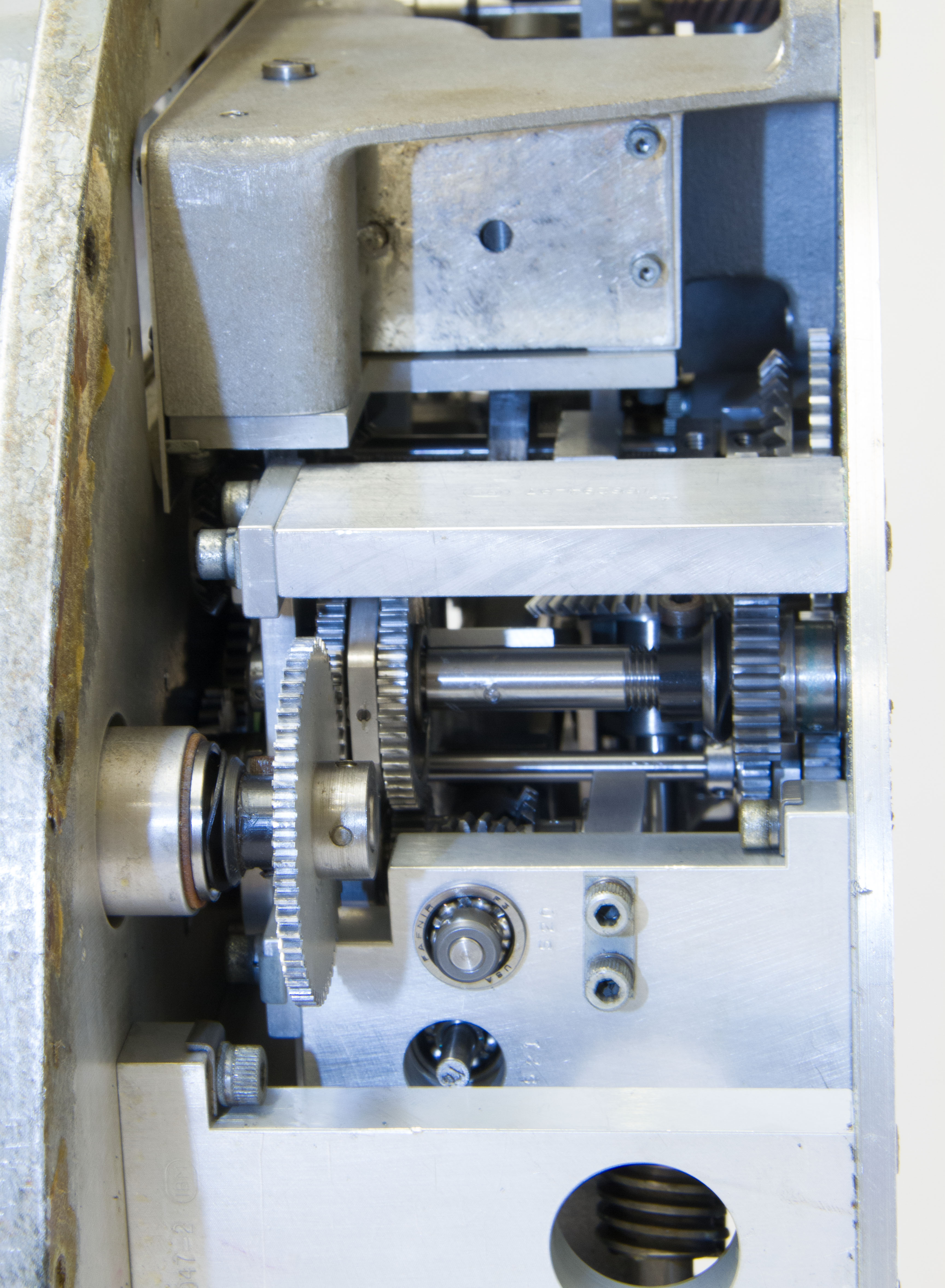
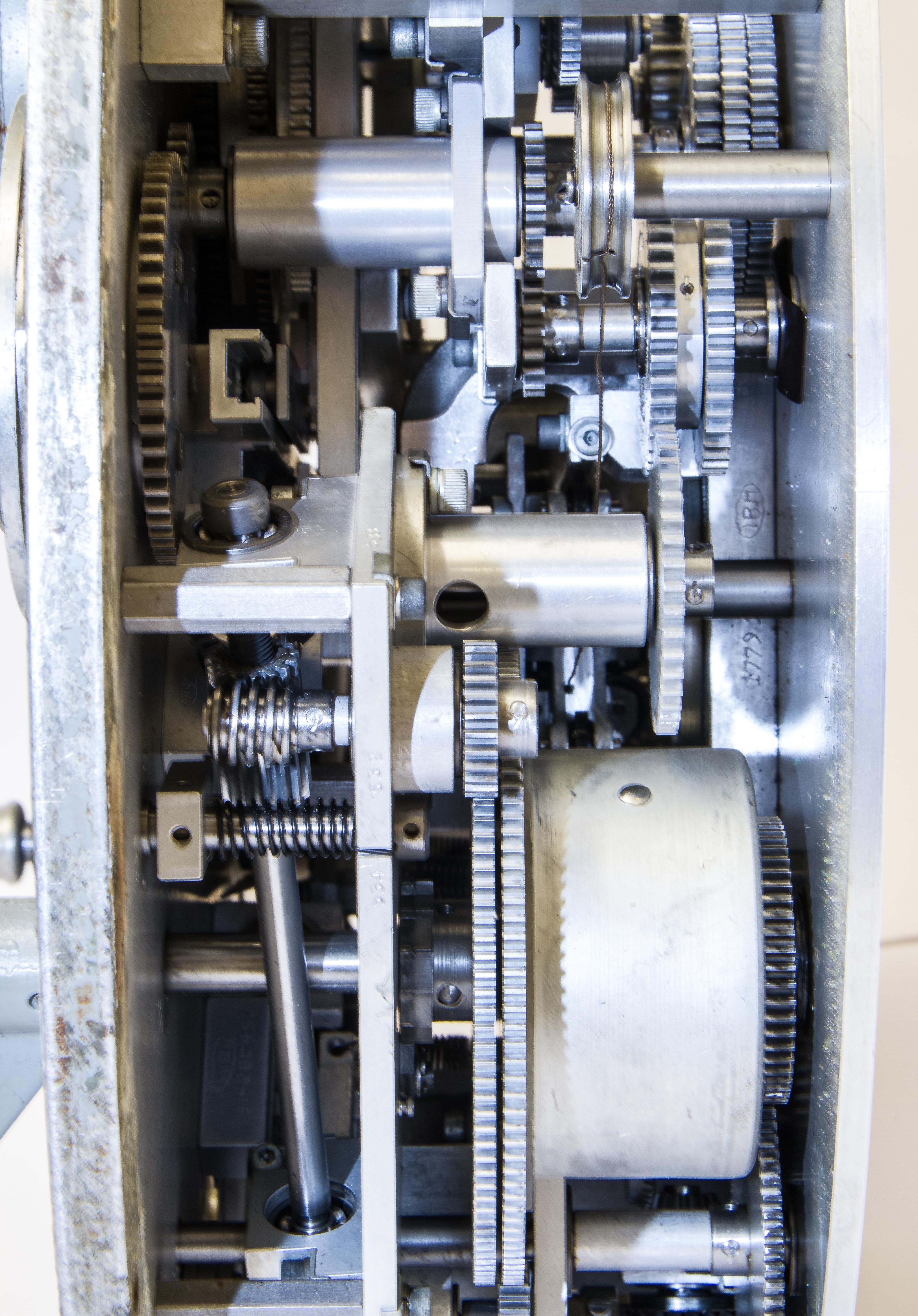
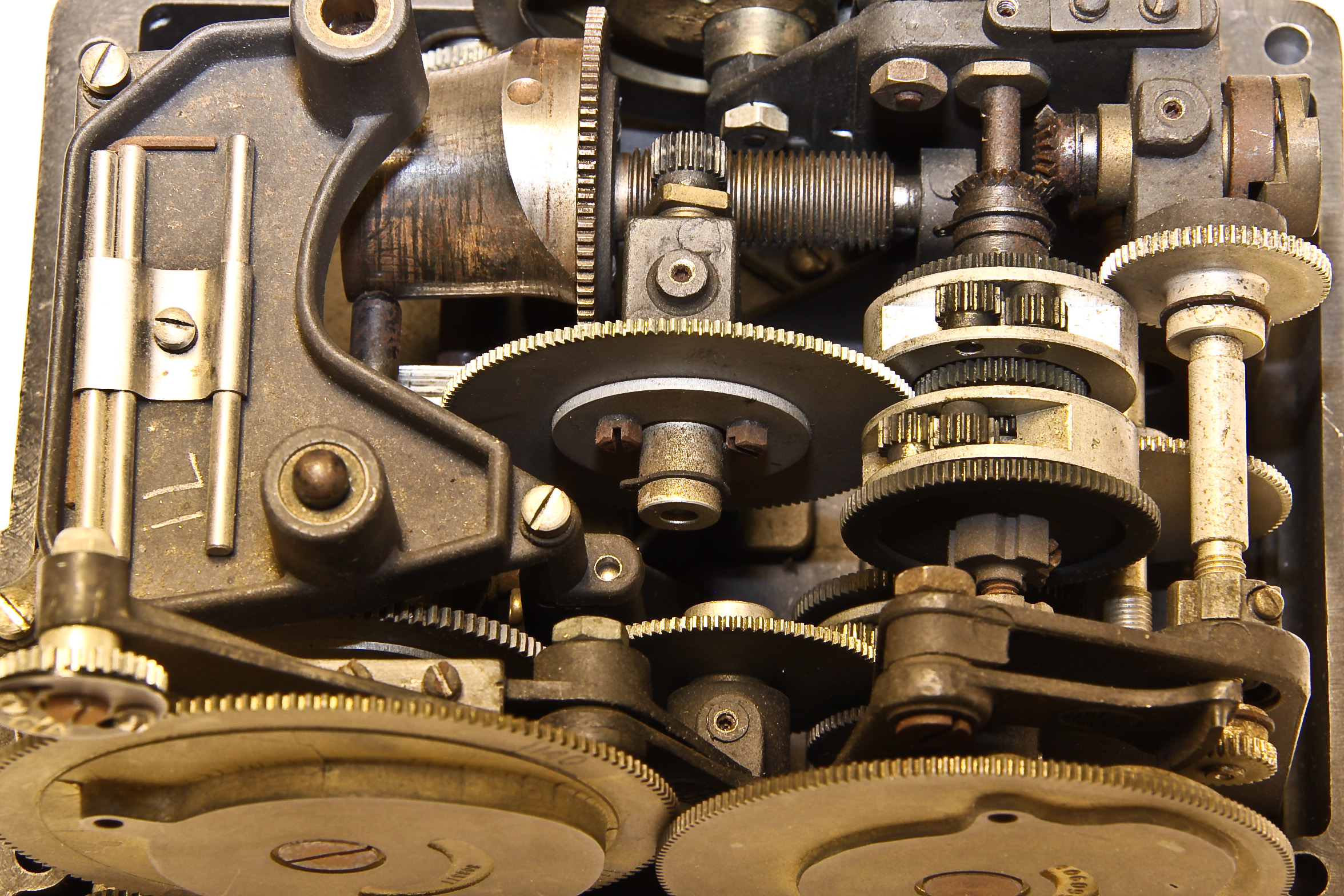
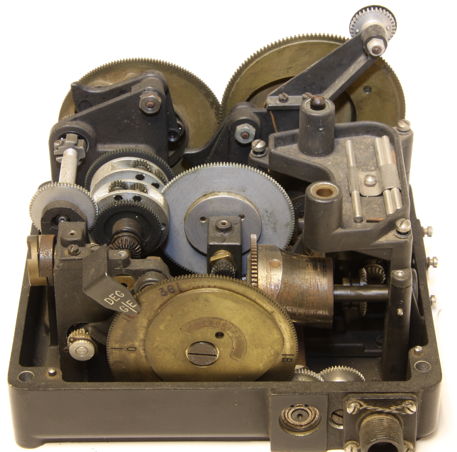
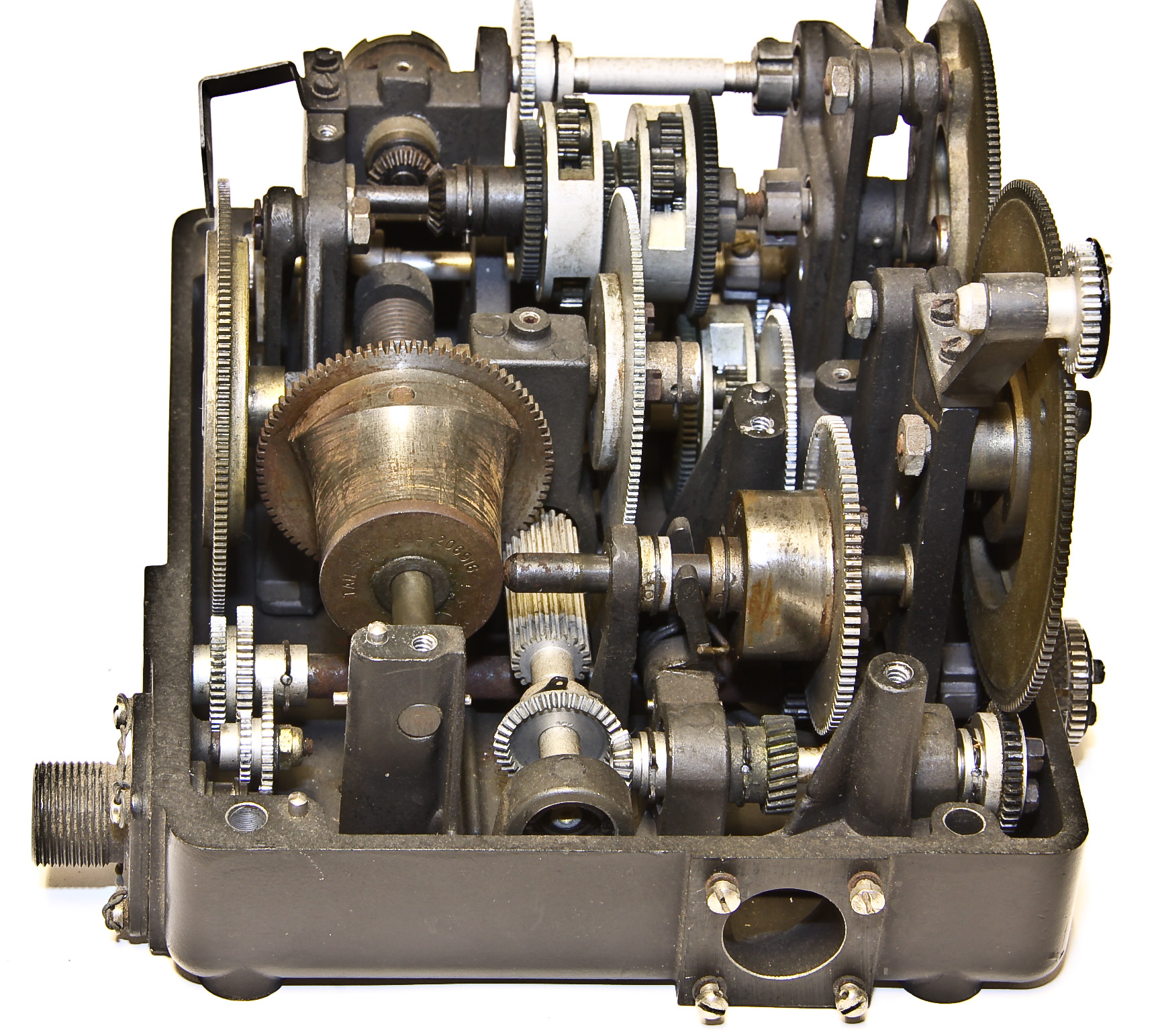
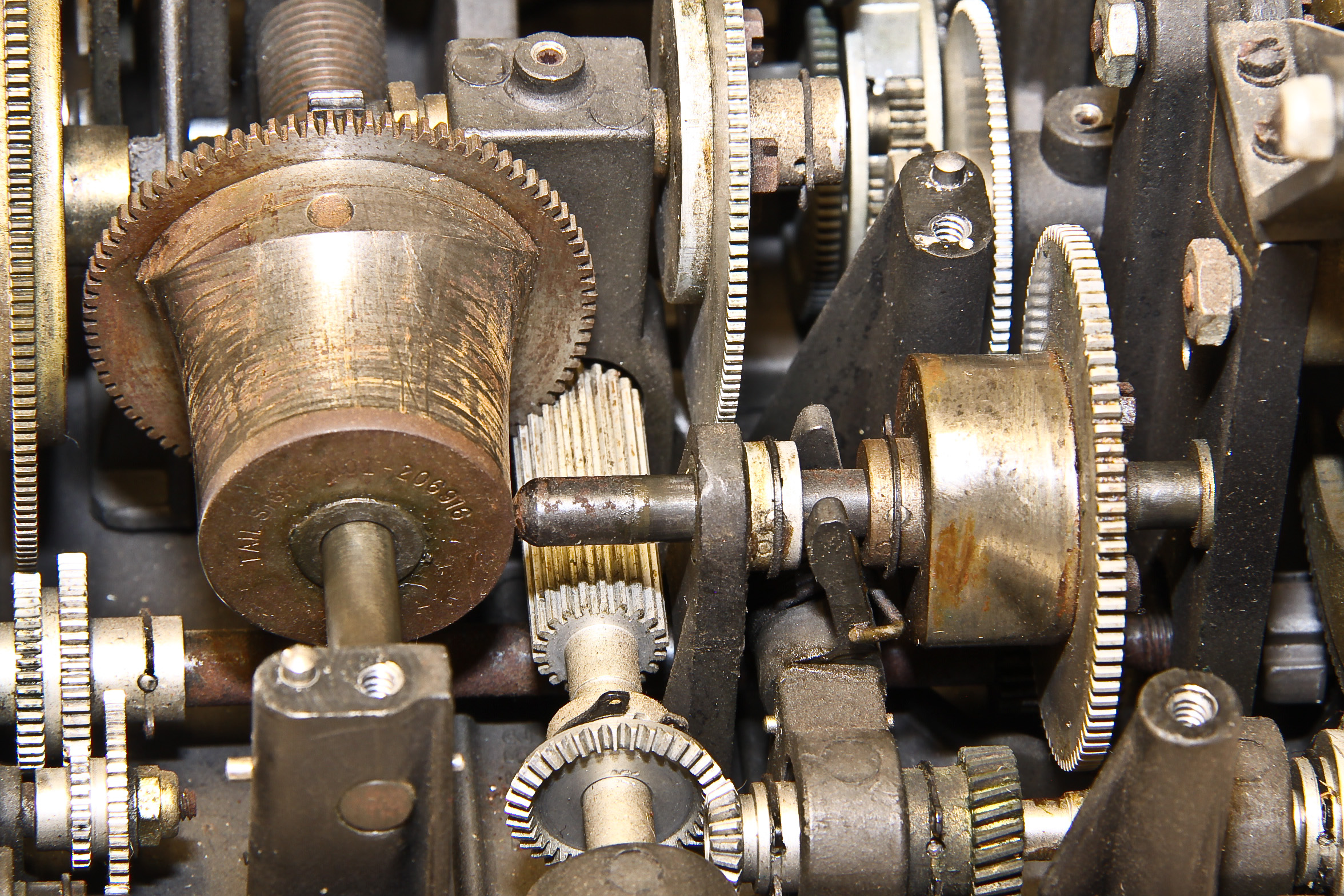
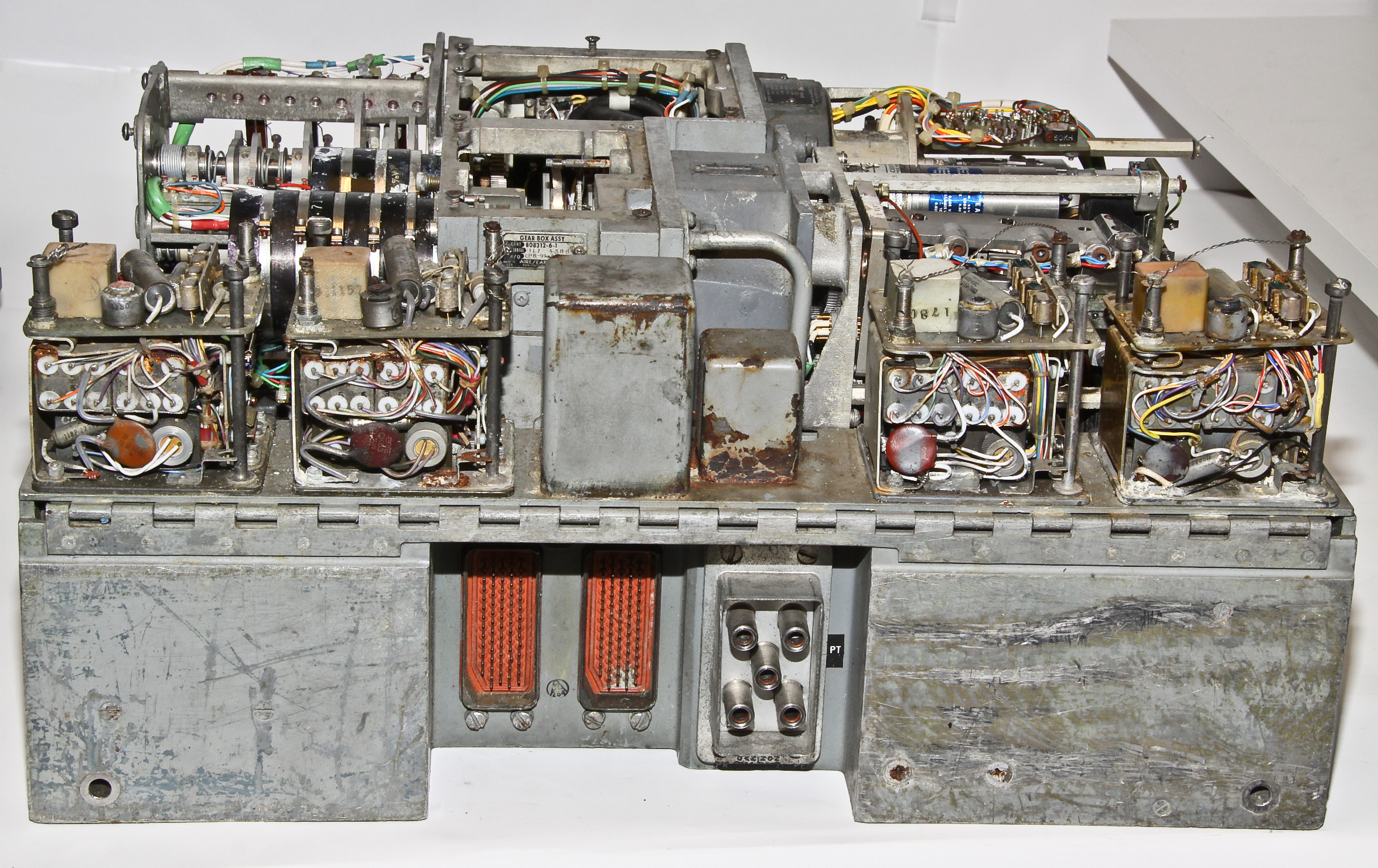
Finally after a lot of physical effort (the bolts were corroded), we have removed its case exposing its innards as shown in Figures 10-15. Figure 11 is a close-up of part of a mechanical multiplier that lies under the ship and target inputs. The spring that powers its calculations is a large cylinder shown in Figures 13 and 14. Near the bottom left of Figure 13 is the governor that tries to produce a constant speed output as the spring unwinds. Figure 15 is the back of the device showing the bearings for some of the mechanisms.
It is obvious from the dirt and marring on the face that this device was used. The insides, however, are pristine! And, the only lubrication is on the spring pedestal (the dark blob on the bottom left of Figure 15).
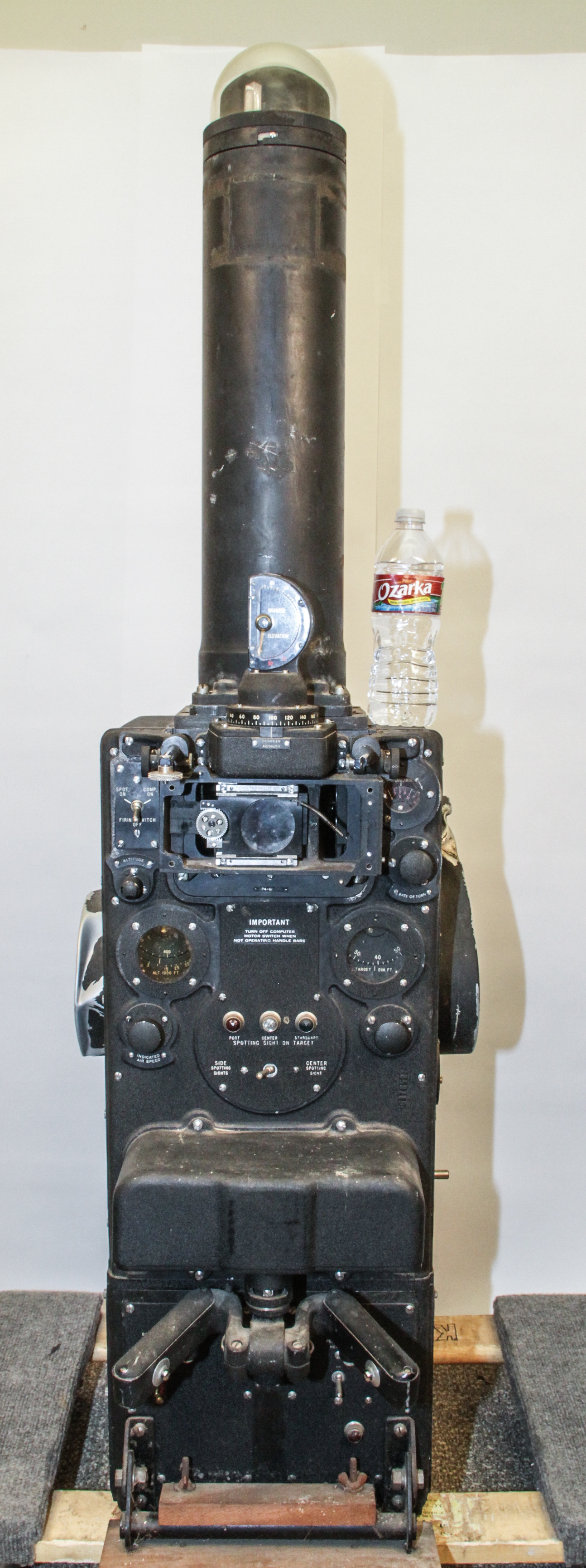
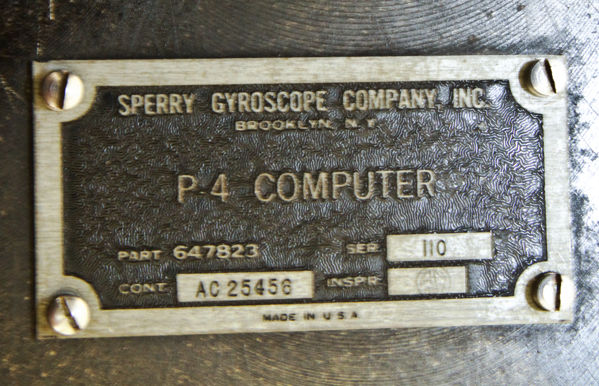
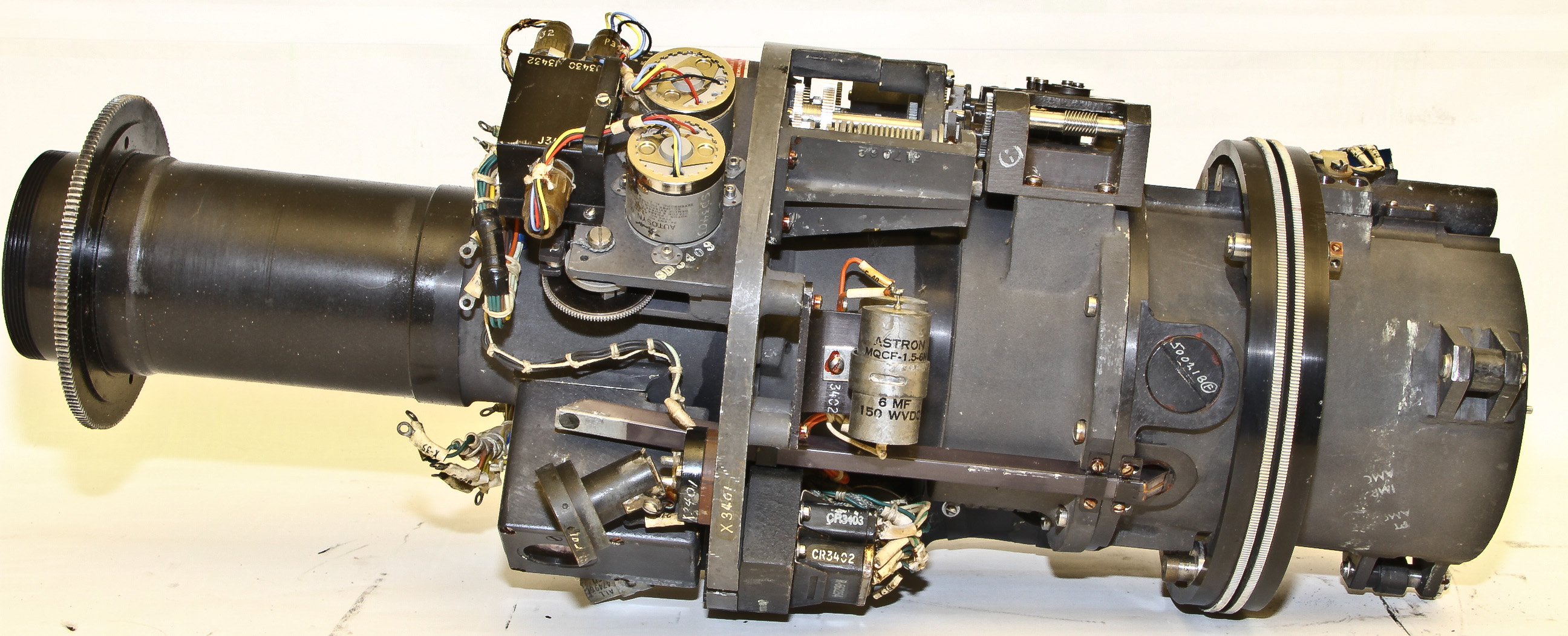
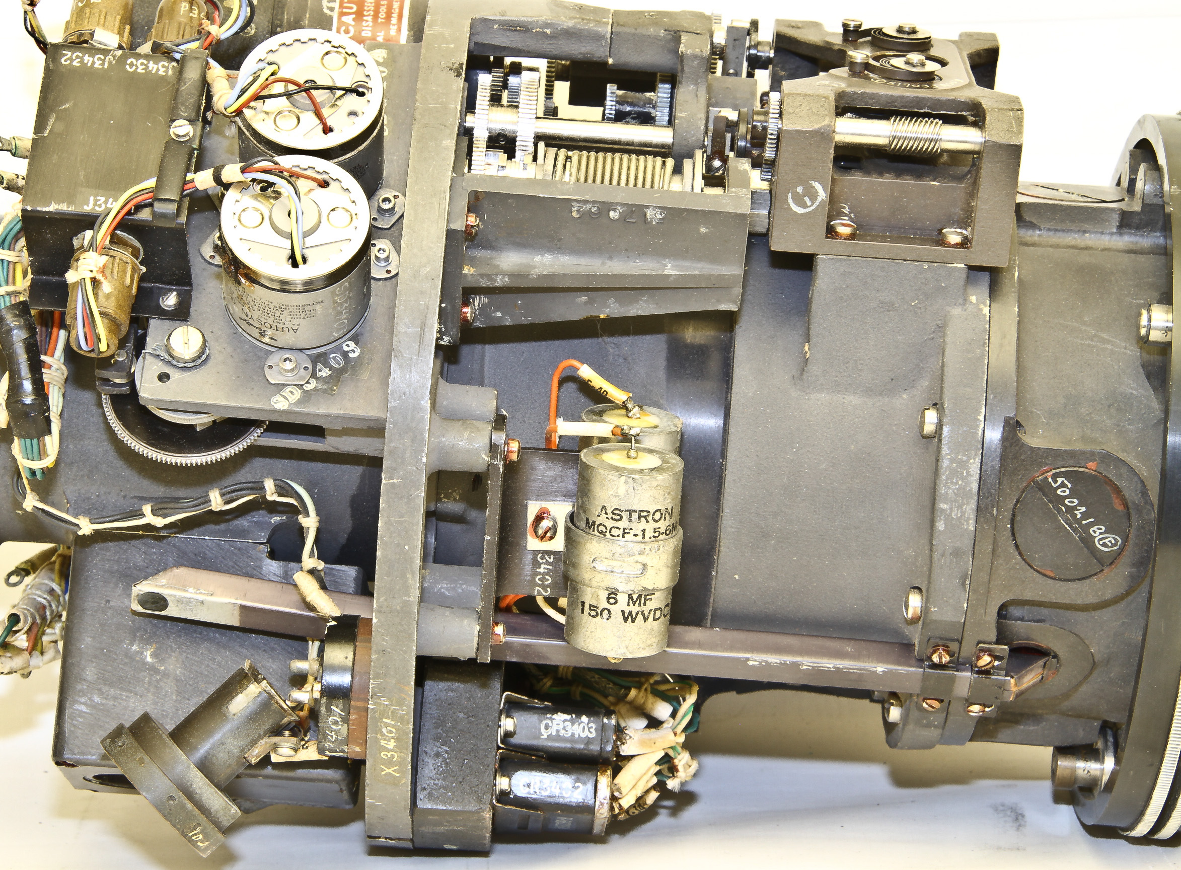
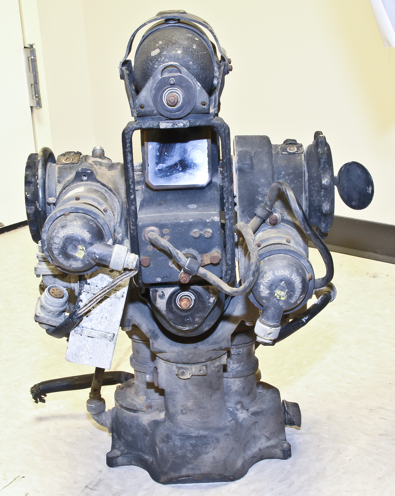
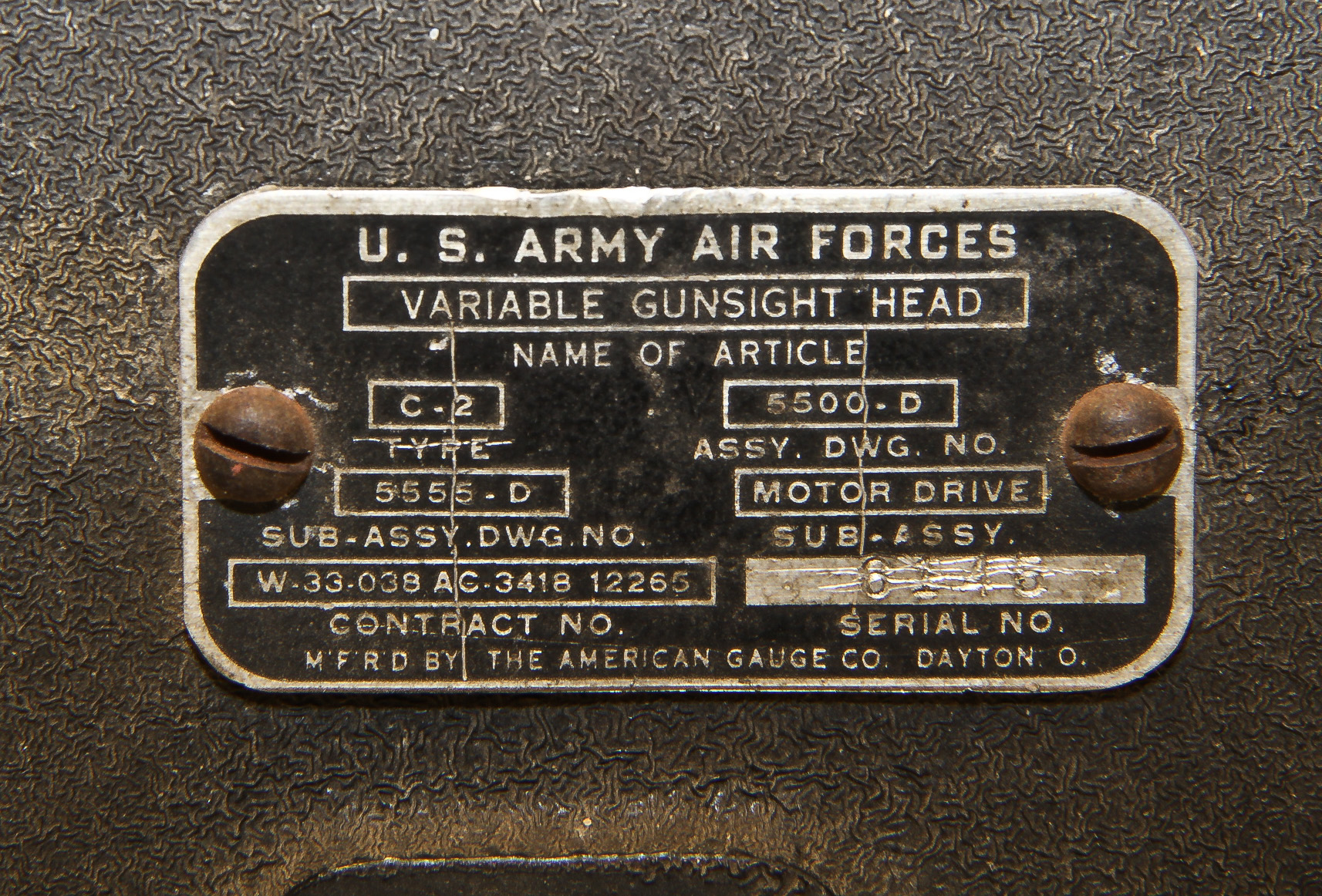
Here is a extremely rare device, an electromechanical Sperry P-4 (Gunsight) Computer. The only good information I could find about this device can be found in this very interesting article describing another museum's (a real one) P4.
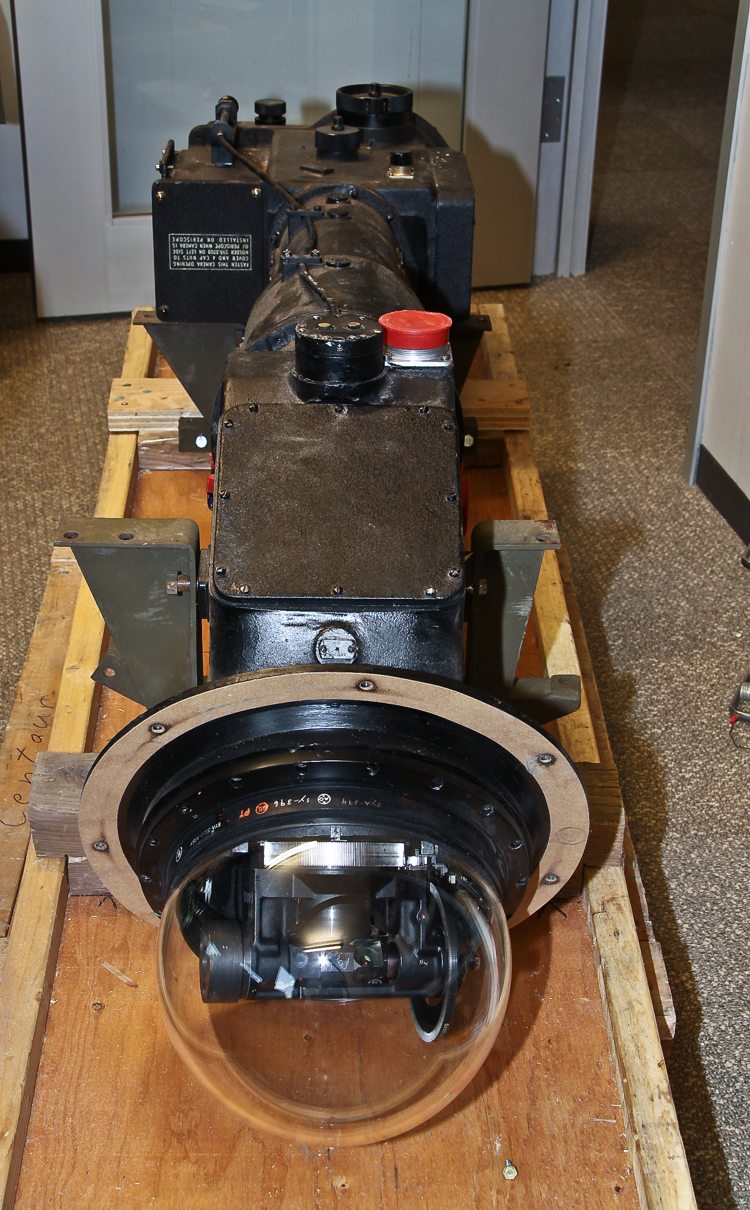
Briefly, the background is that the P-4 was originally designed as part of a central fire control system for the remote control of bomber gun turrets primarily for the B-29 and B-32 bombers (the B-32 was a backup in case of problems with the B-29 program). Ultimately, the Sperry P-4 was not chosen by the Army and was replaced by the GE-designed fire control system covered elsewhere in the museum. According to the referenced article, only 460 P-4 systems were contracted for and the number actually built out of these 460 is unknown as the contract was canceled before they were all built. There were several factors that lead to the GE system being chosen, including P-4 schedule delays, but one of the most critical was the small field of view from the periscope.
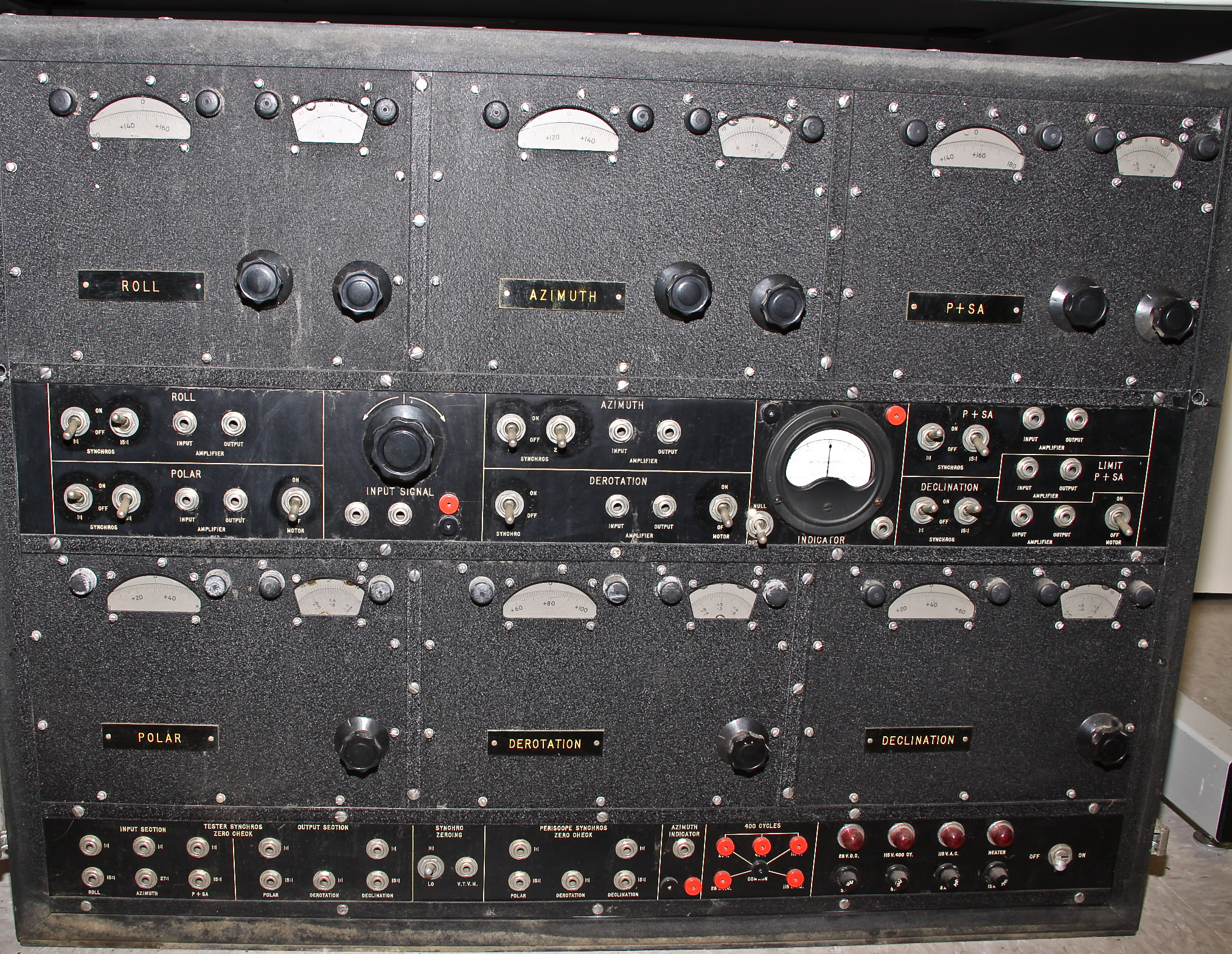
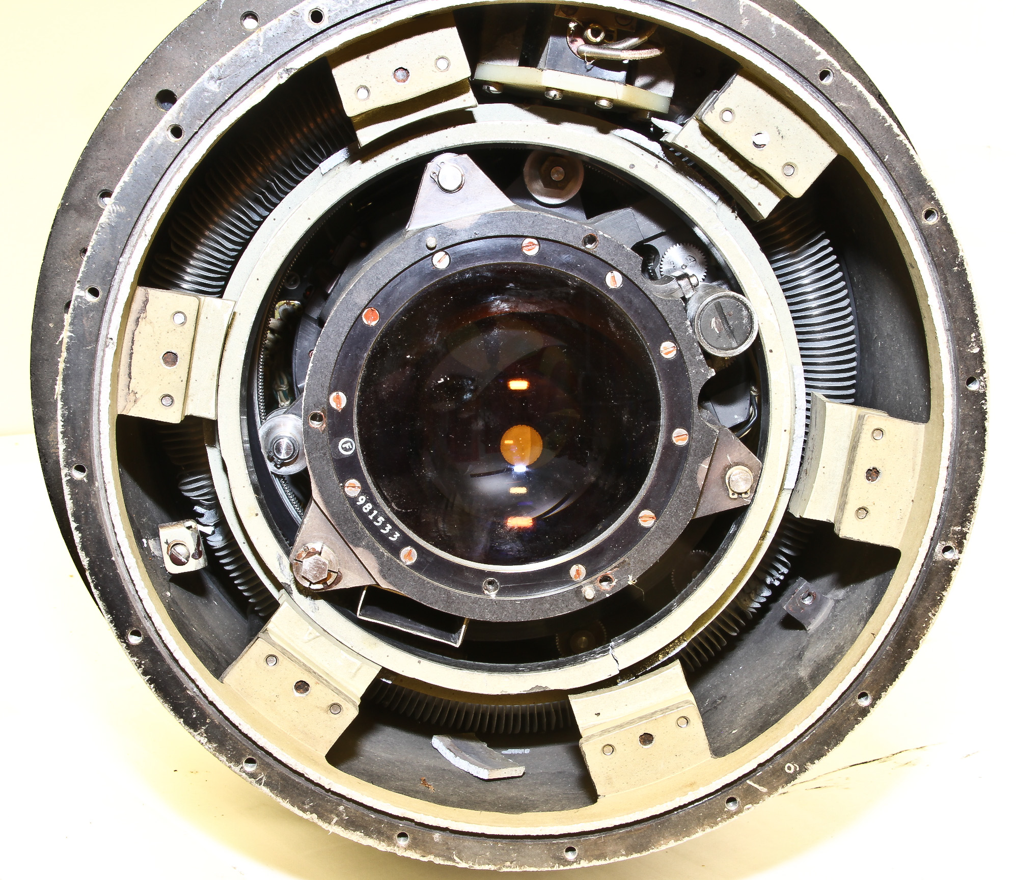
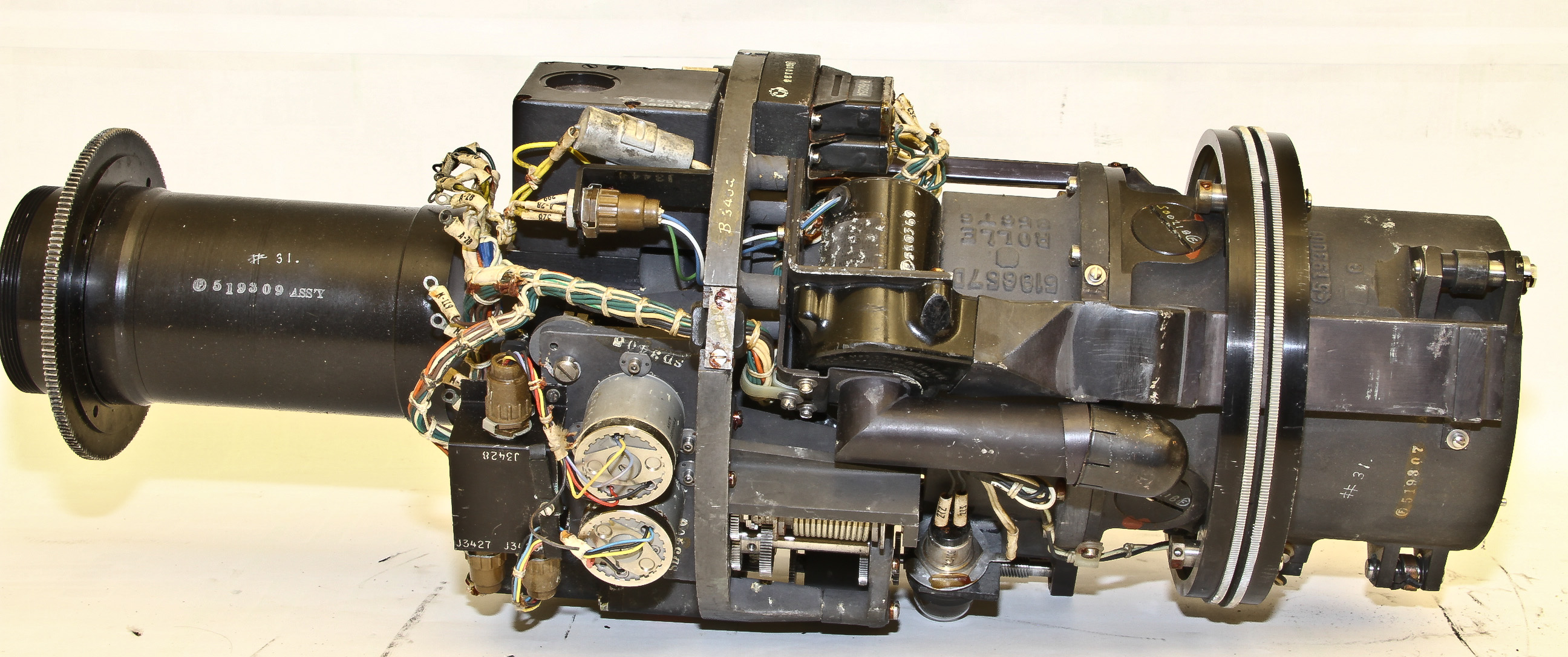
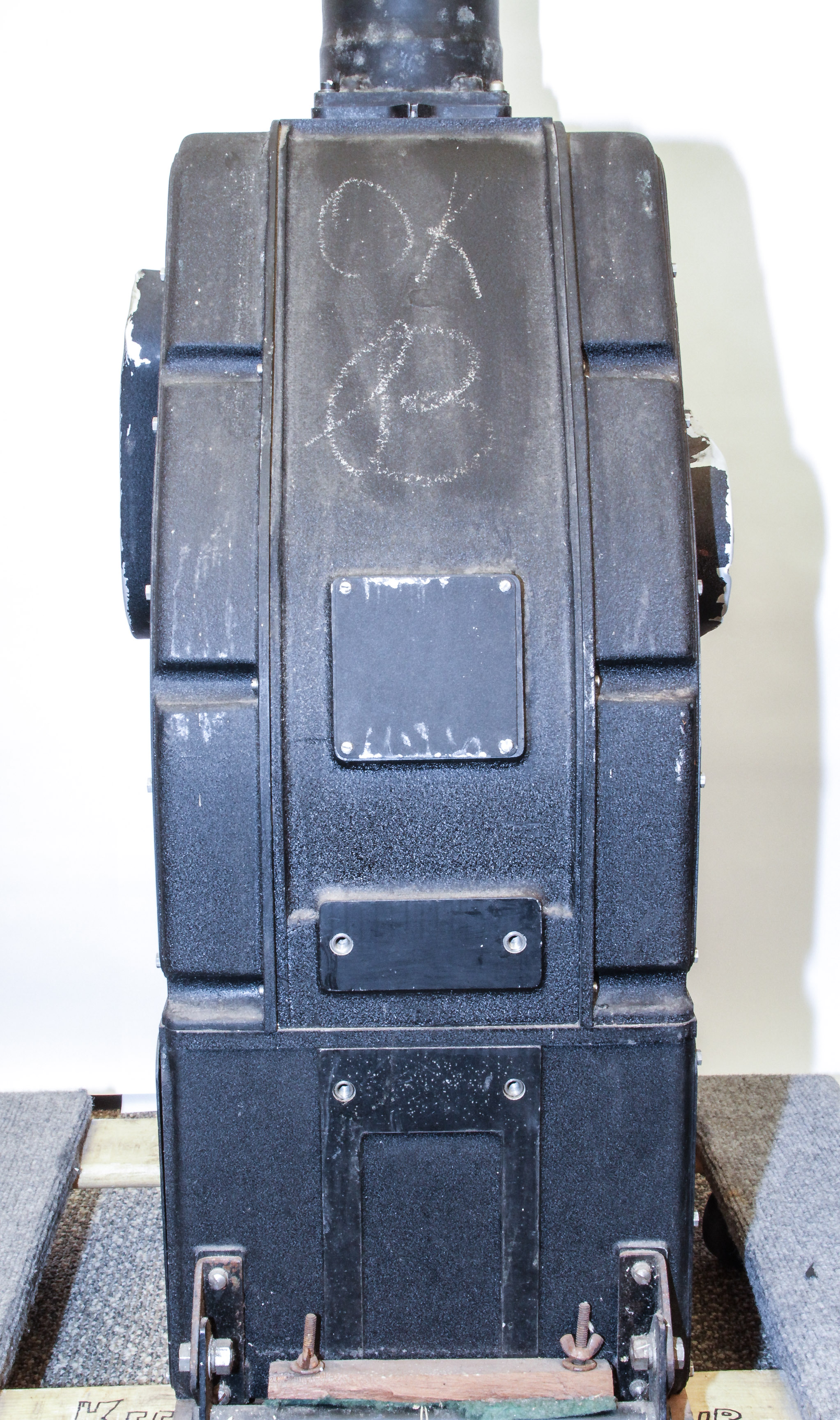
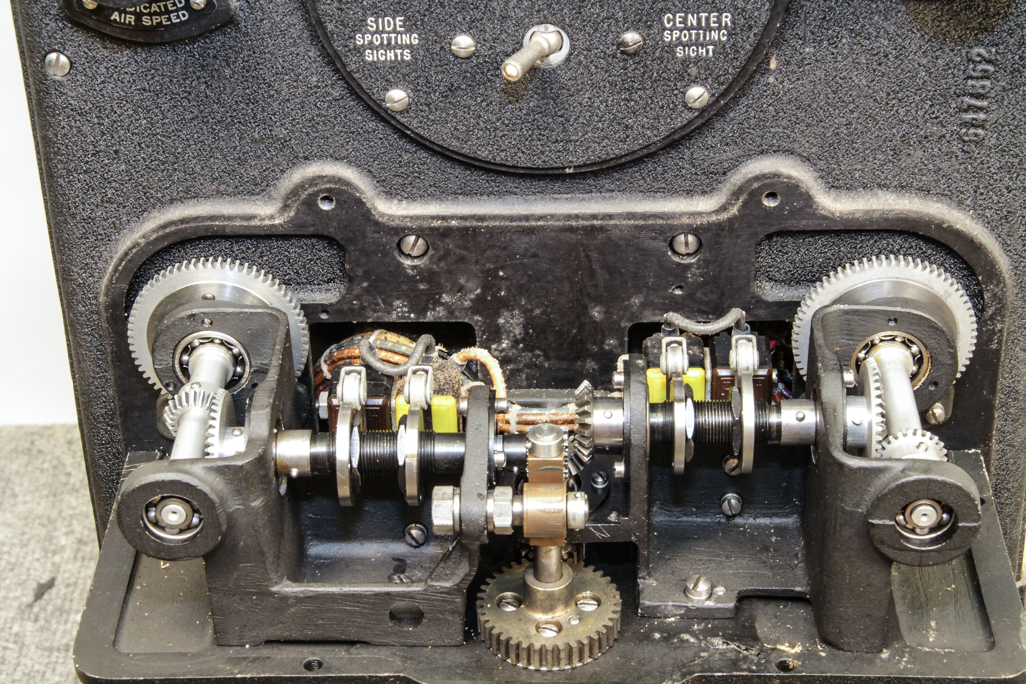
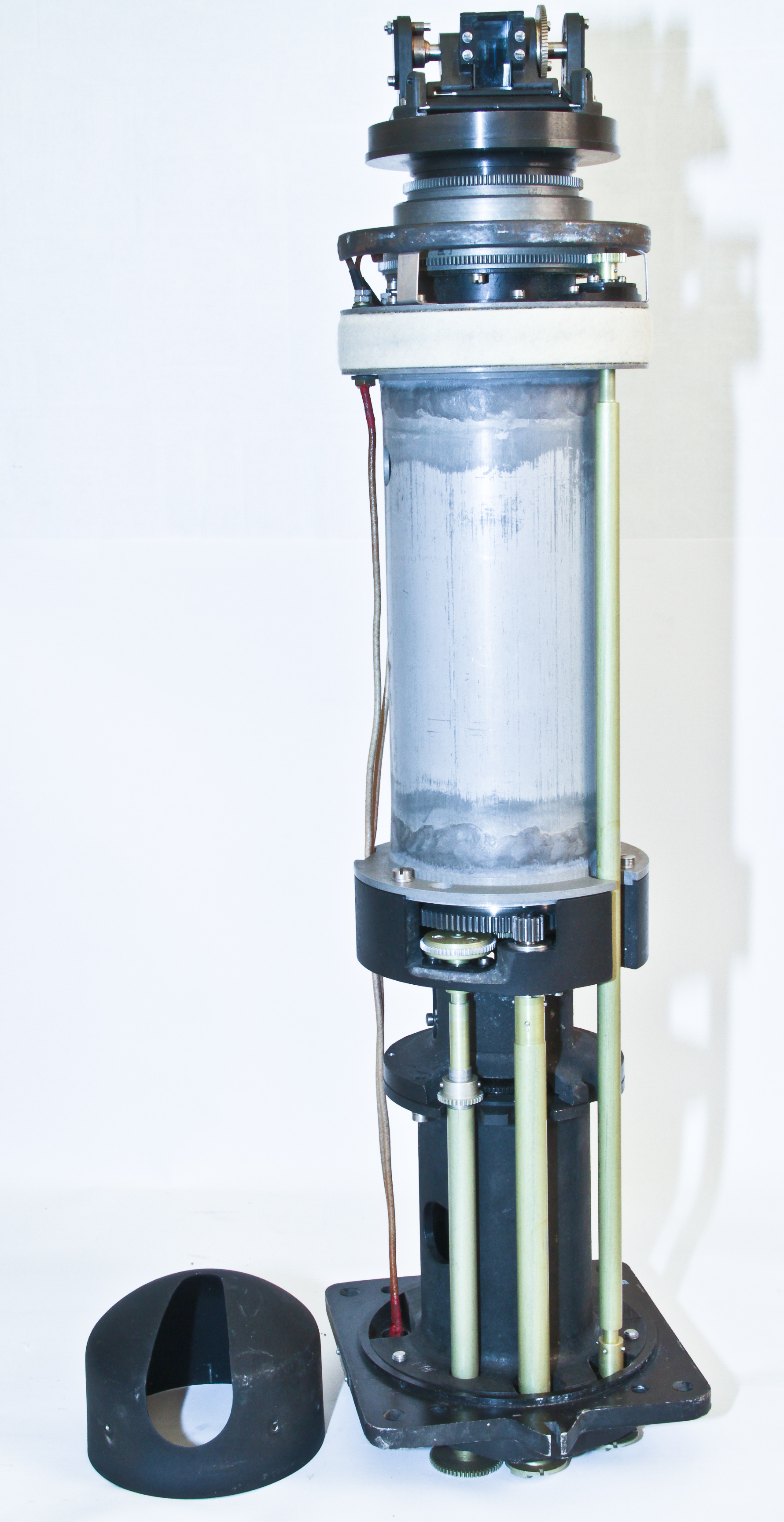
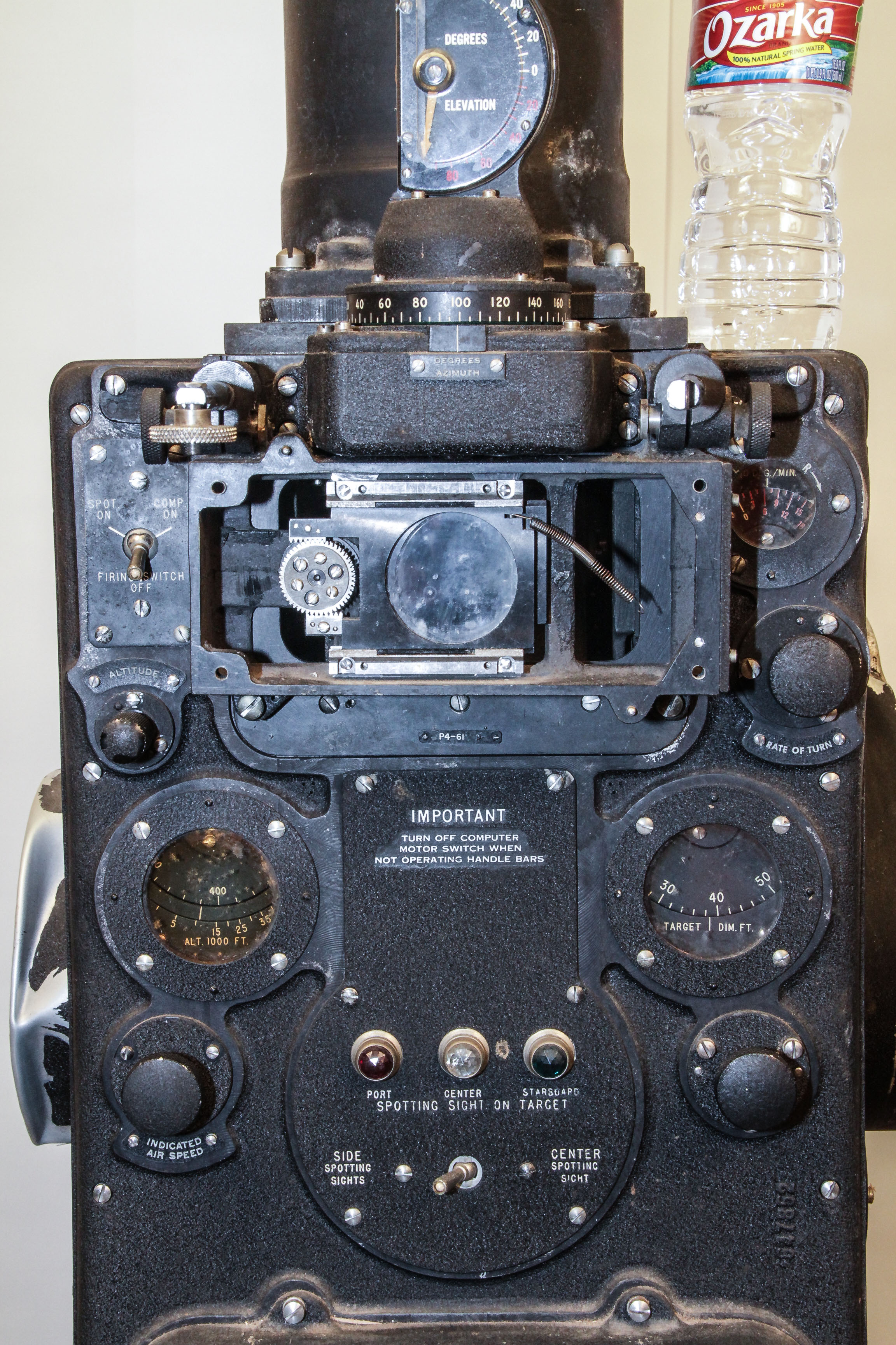
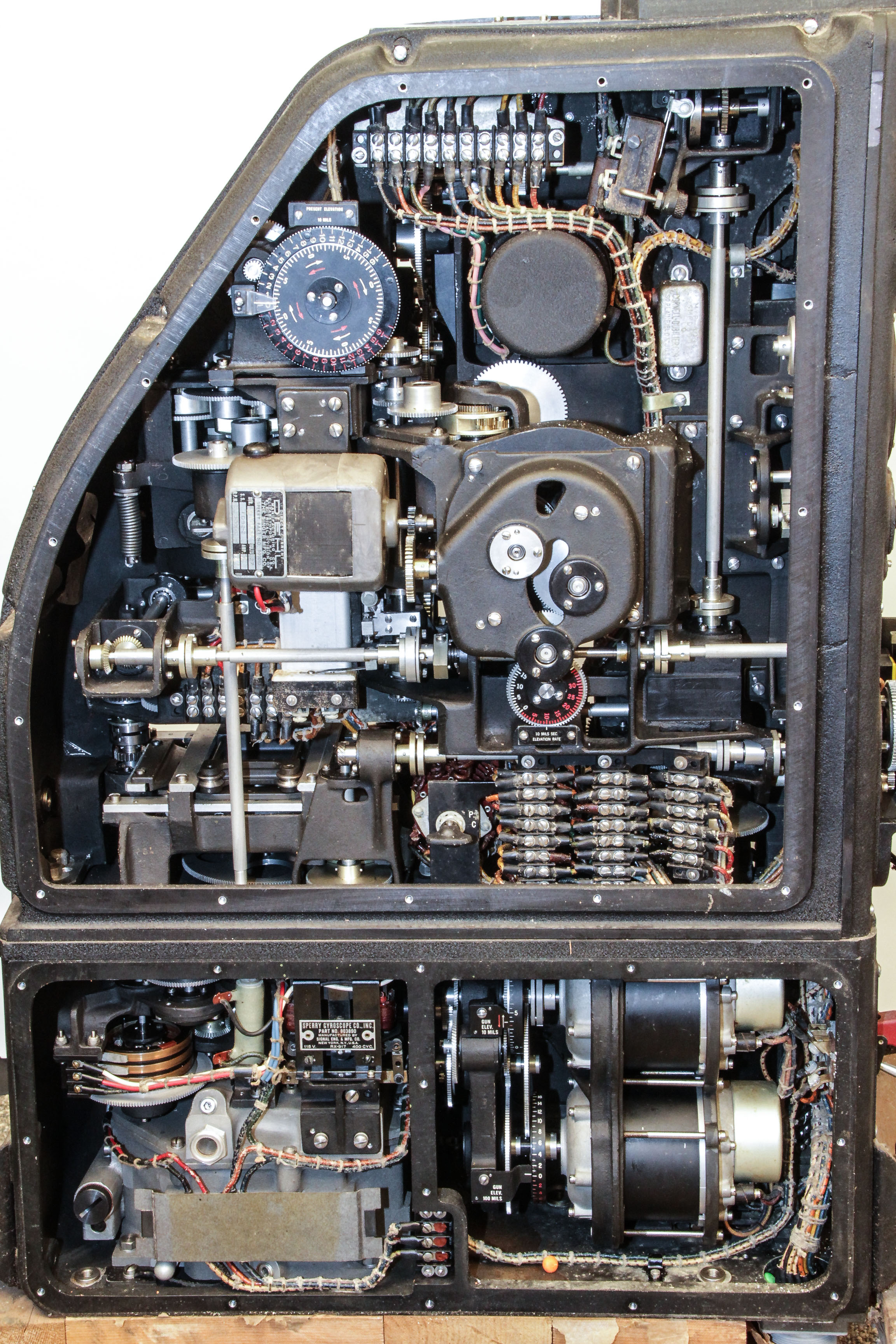
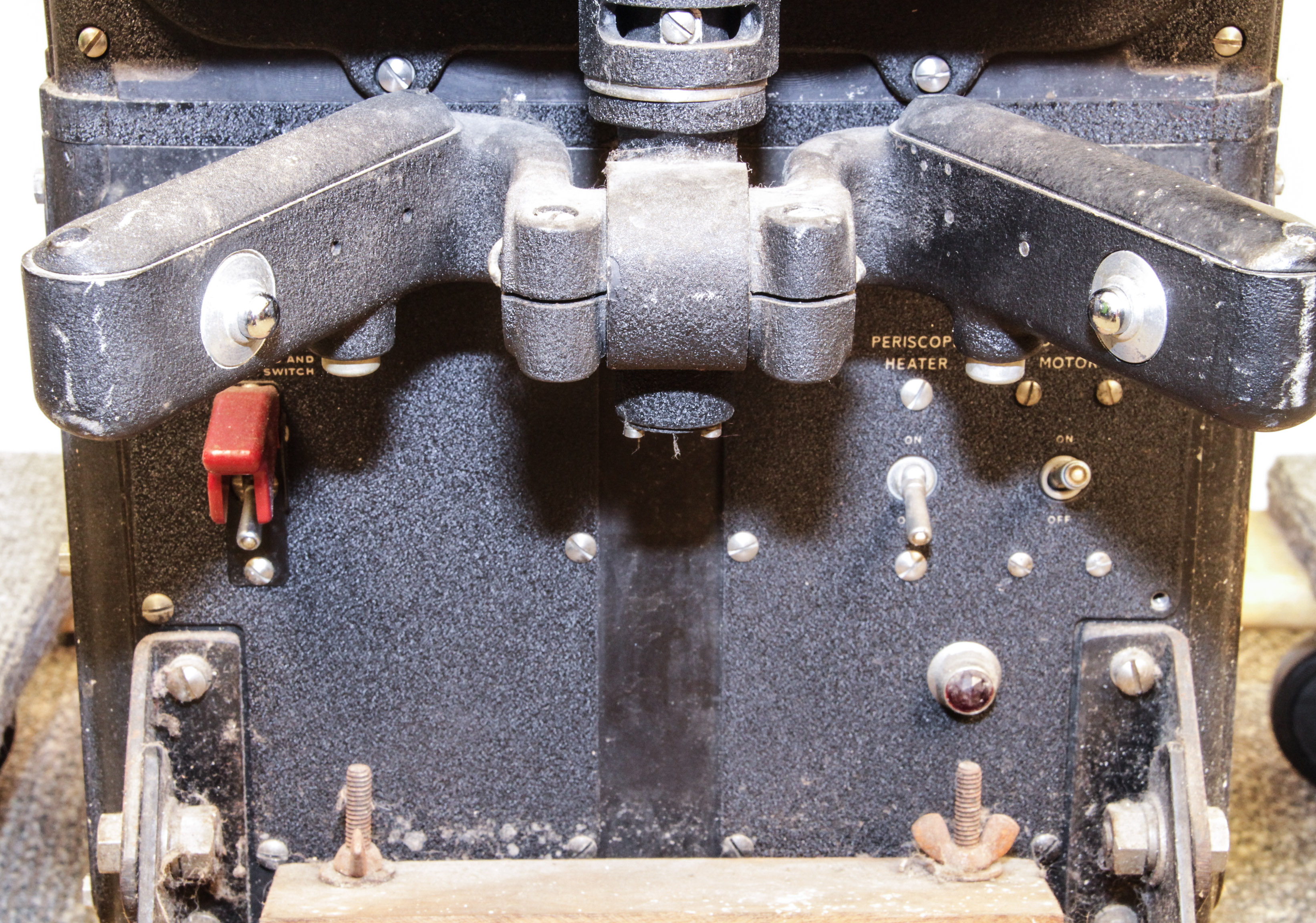
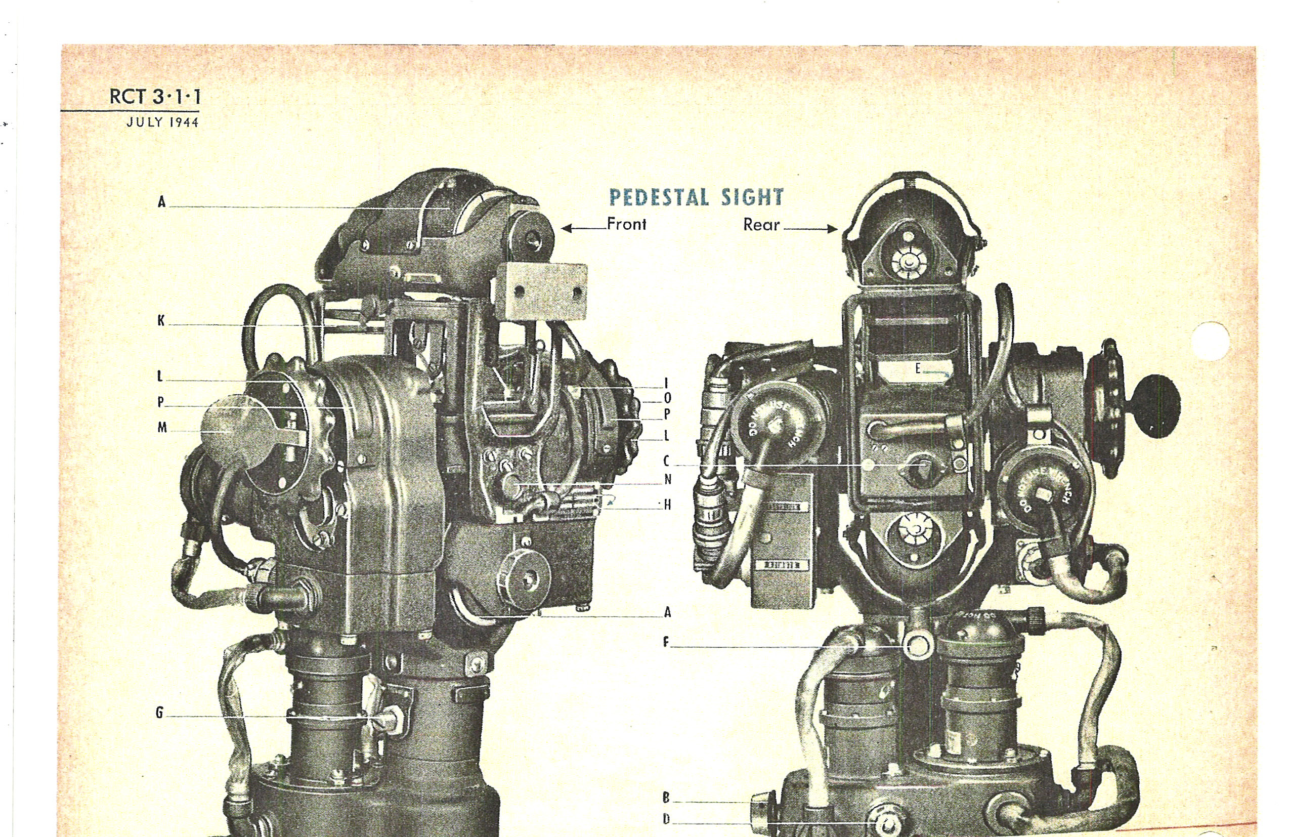
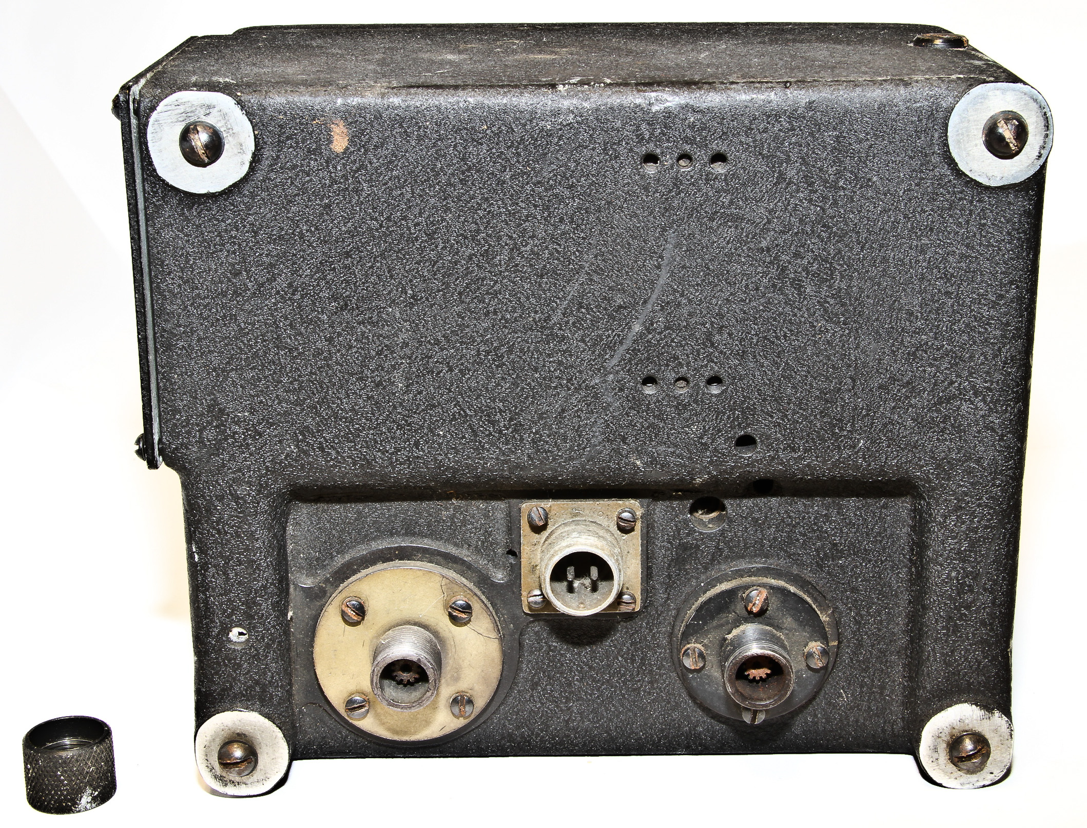
Our P-4 is about six-feet tall and weights about 200 pounds!. Figure 1 shows the front of the entire device (a water bottle show the scale). The periscope on the top looked out through a window on the top of the centrally located sighting compartment on the plane. Just below the base of the periscope, Figure 2 shows the eyepiece for viewing (our device is missing part of the the eyepiece), and the controls and readouts for items like airspeed and altitude. Below that, shown in Figure 6, are the steering controls for manipulating the left-right and up-down of the view through the periscope. Figure 7 show the mechanism to translate the control movements. Figure 3 show the back of the device, slanted (as can be seen in Figures 4 and 5) to fit (I guess) the upper curve of the fuselage. There was also a foot pedal connected to a rod on the side for zooming the view. Our device is missing this foot pedal. It also has damaged side panels. Otherwise, the insides seem pristine: in Figure 8 notice the grease on the three-dimensional cams.
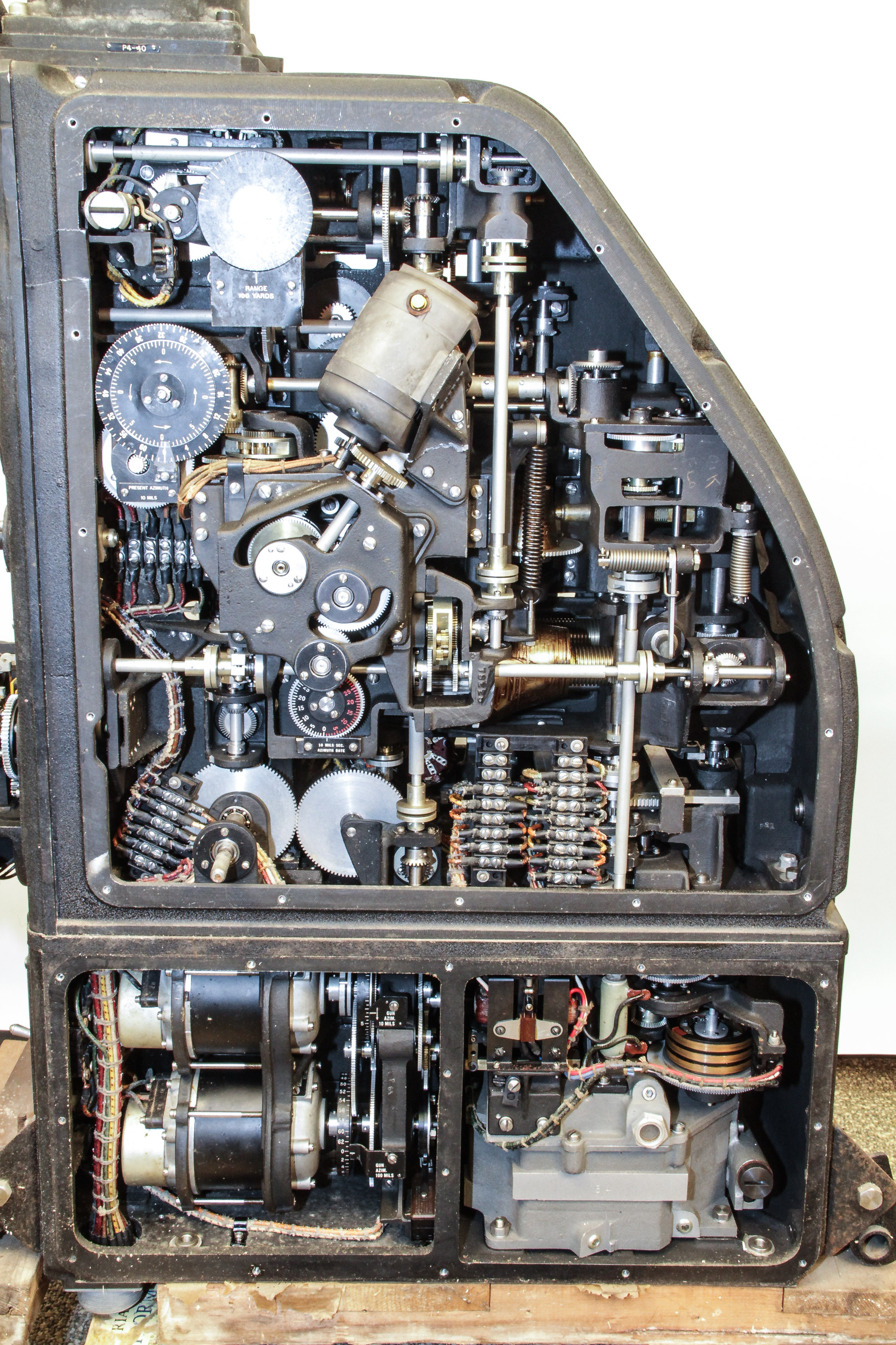
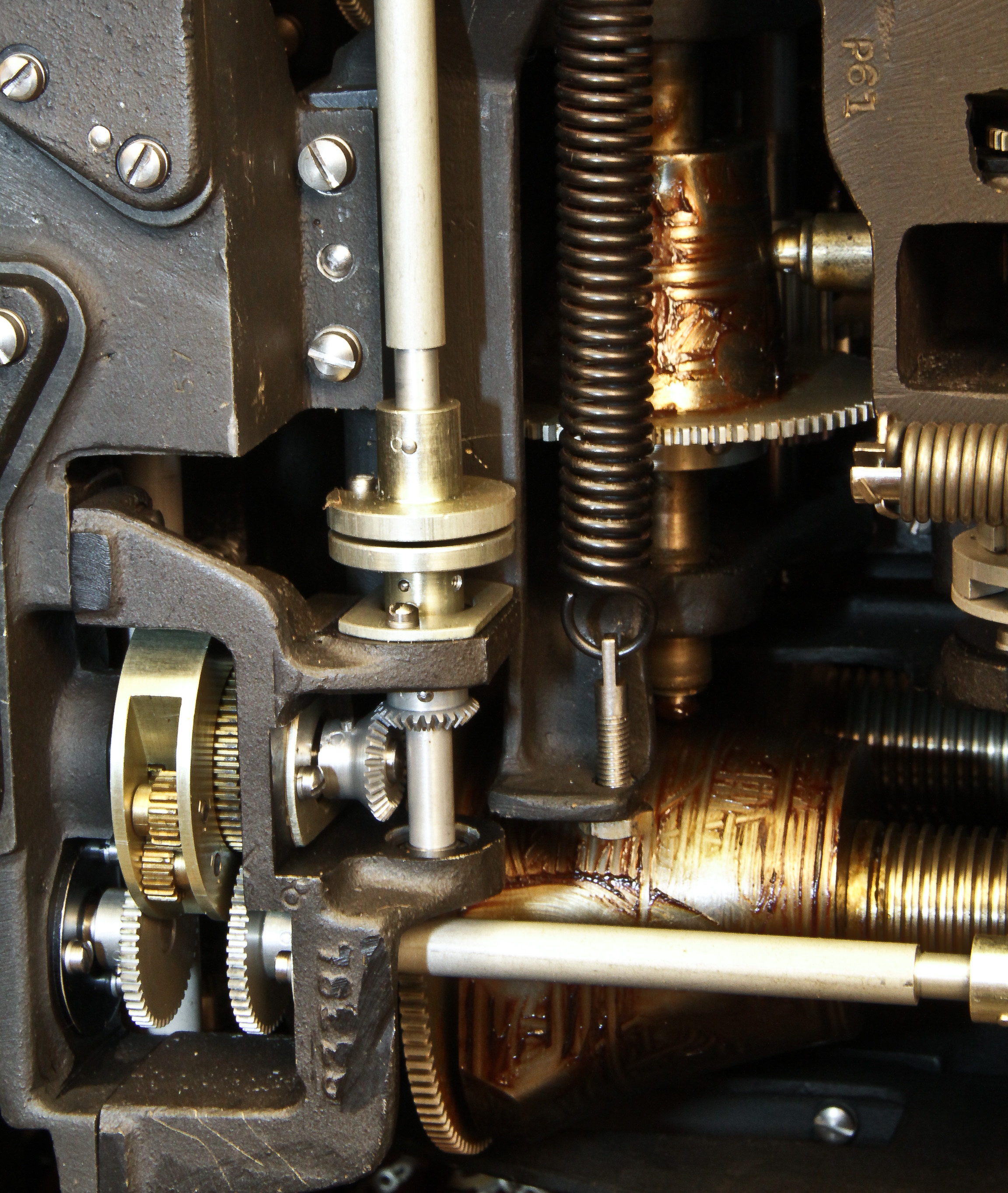
The real interest is the internal computing mechanisms show in the side views of Figures 4 and 5 (obviously the side panels have been removed.). In person, the details are very impressive. Much of the mechanical computing elements are not easily seen in these pictures. Figure 8 is just one example of the complexity that lies deeper within the case.
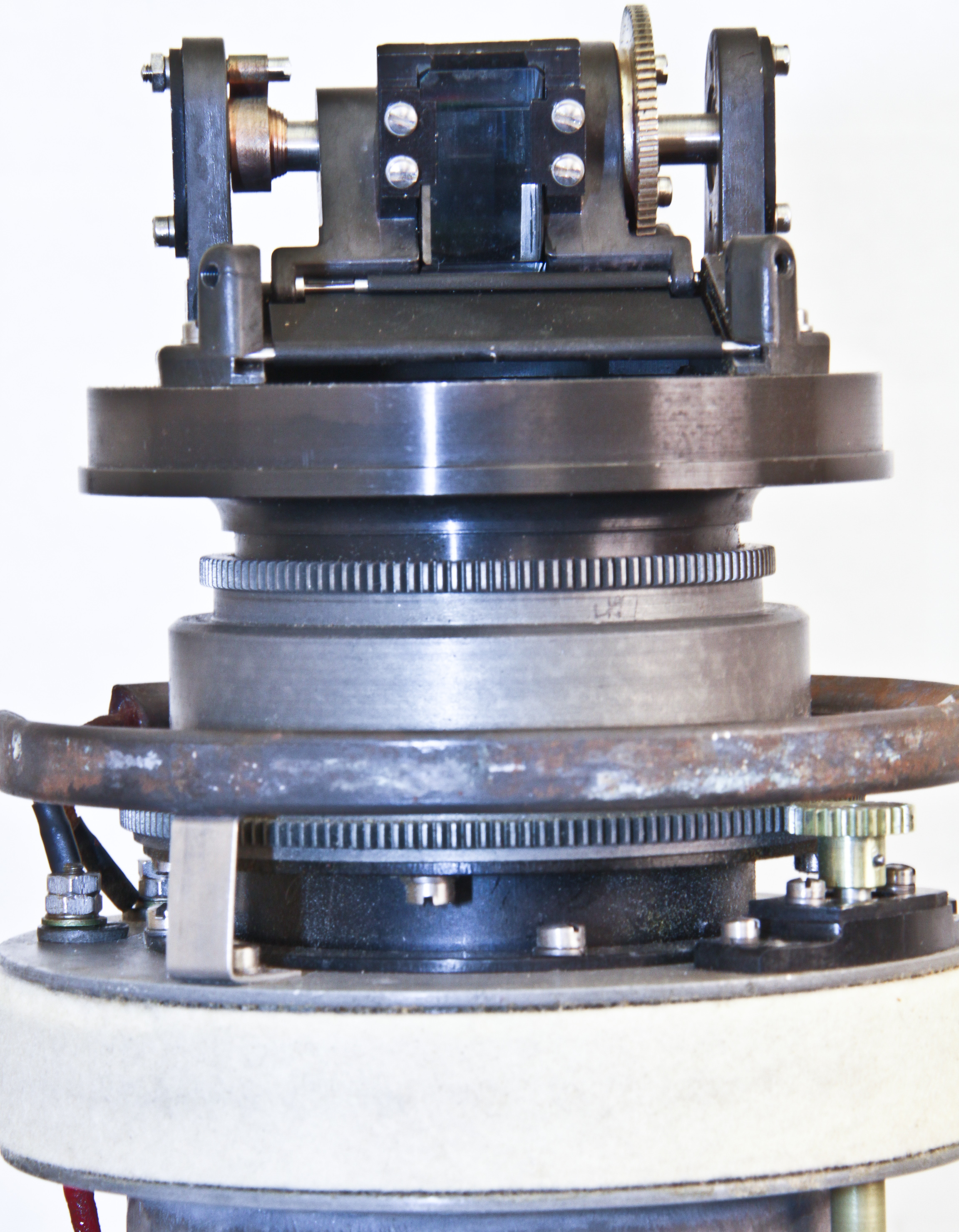
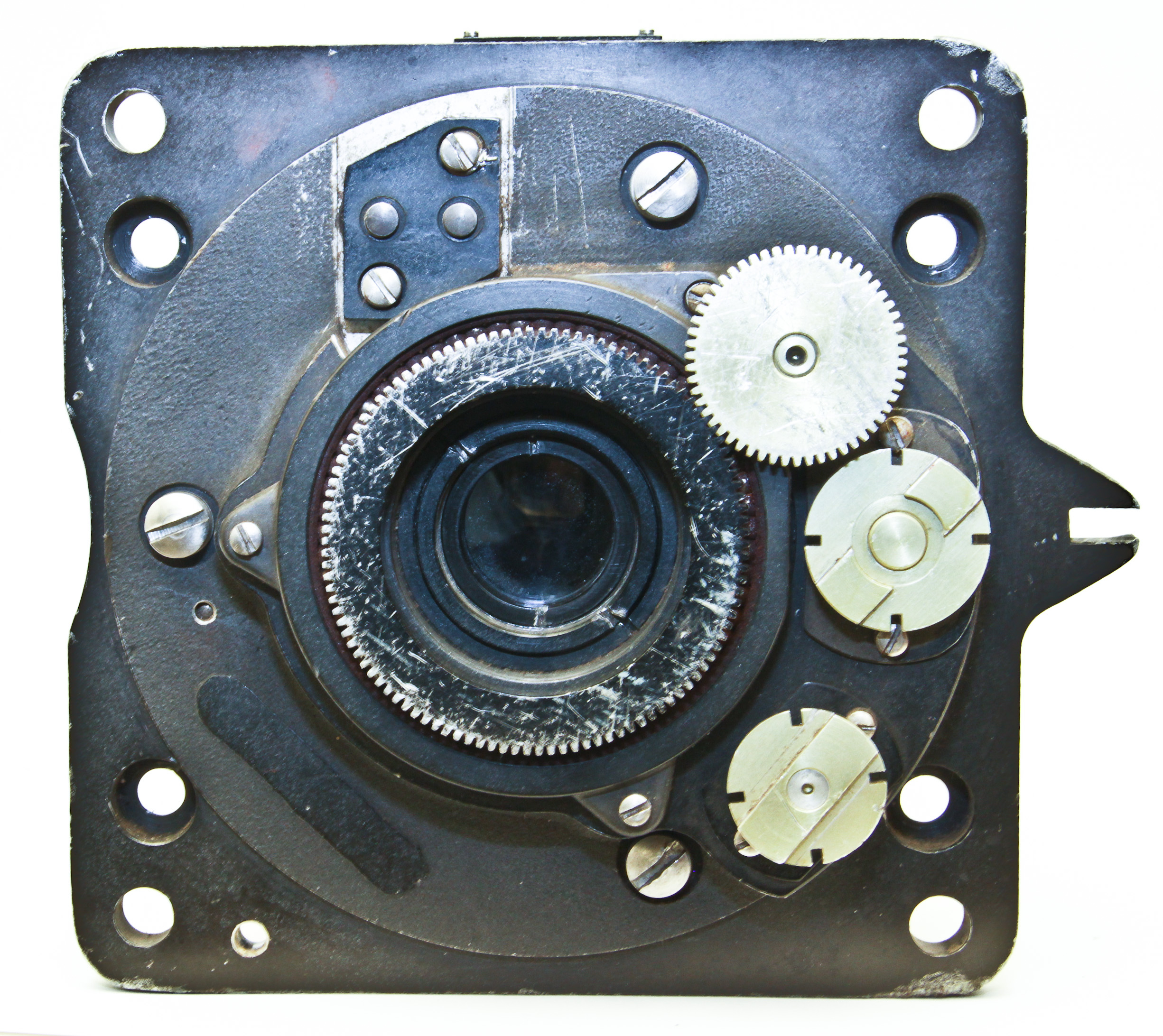
Figures 10,11, and 12 show the periscope with its case removed. There are three controls attaching to the computer unit: pan, tilt, and zoom. These controls is transferred from three rods that attach to matings at the bottom of the periscope. There is also a heating element. Note the very small optical element (a prism); it is about the size of a thumbnail.
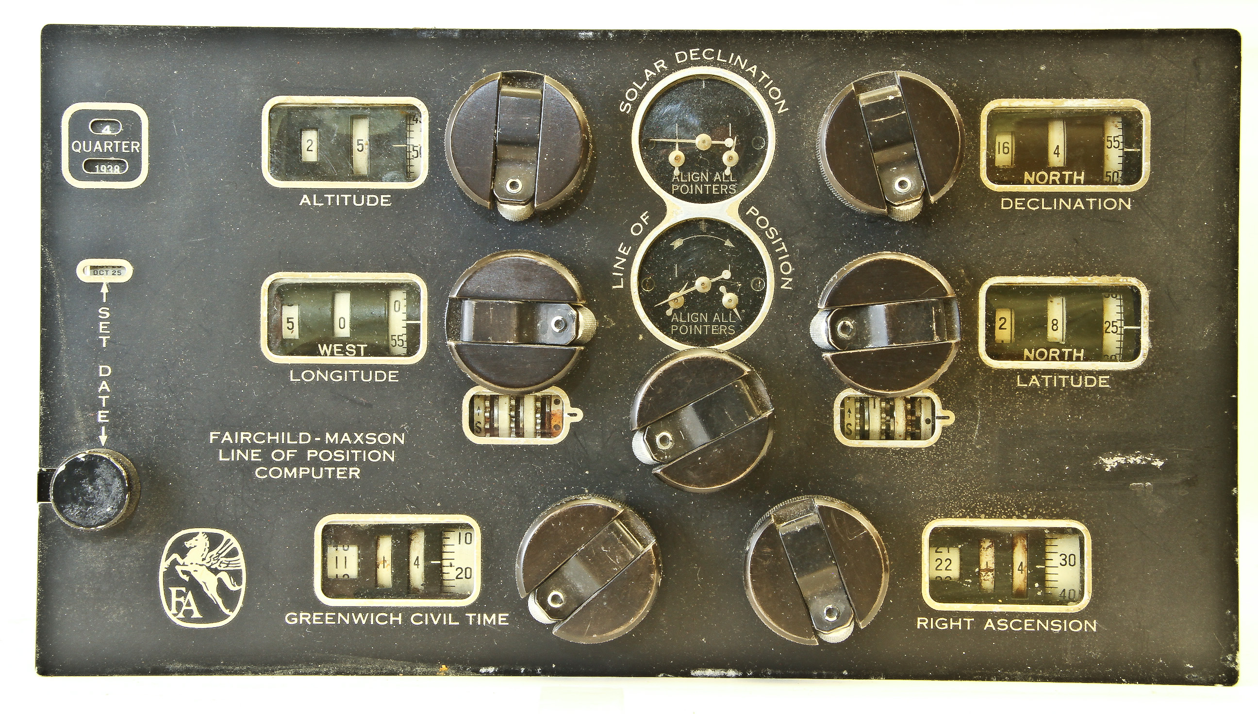

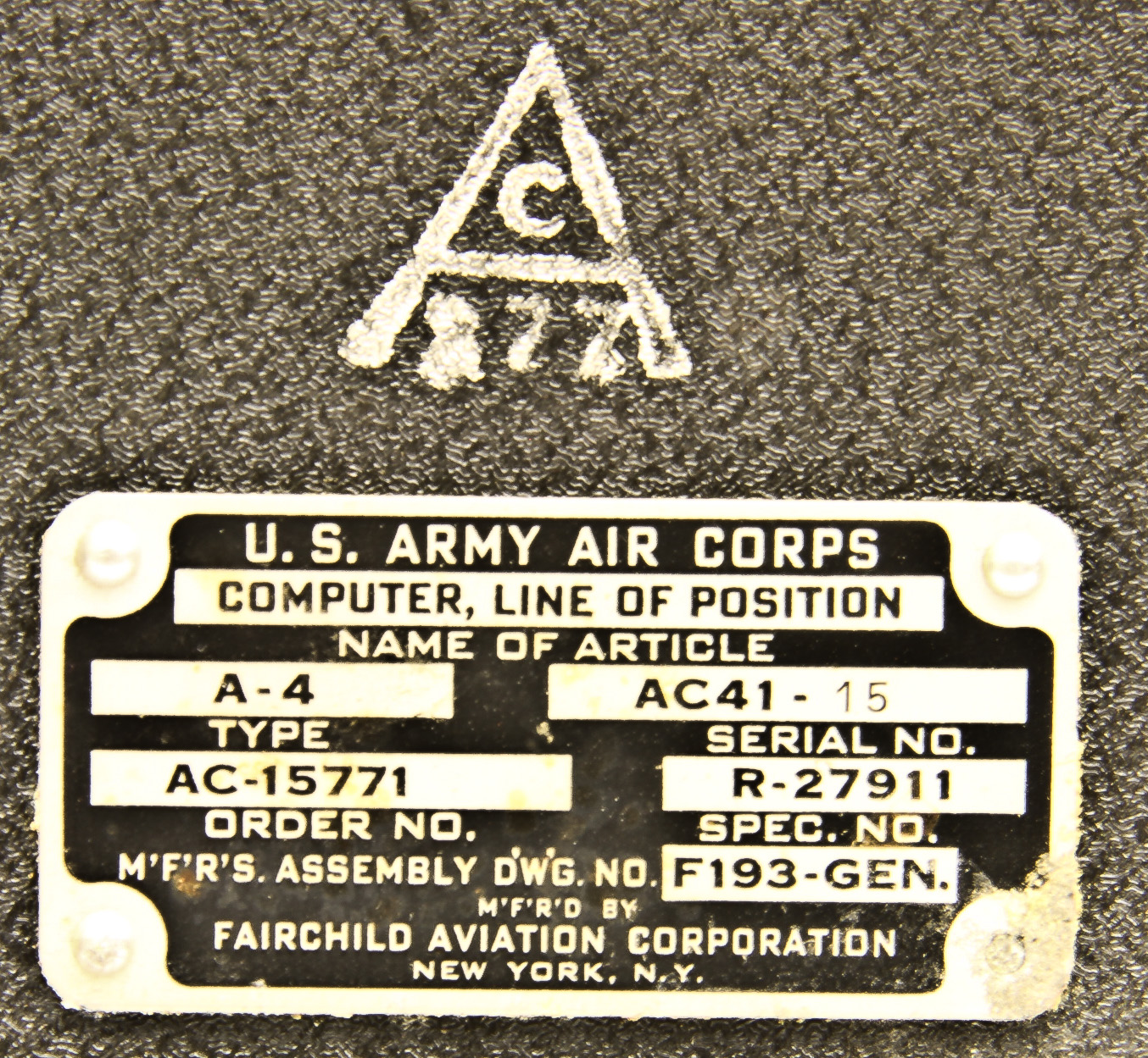
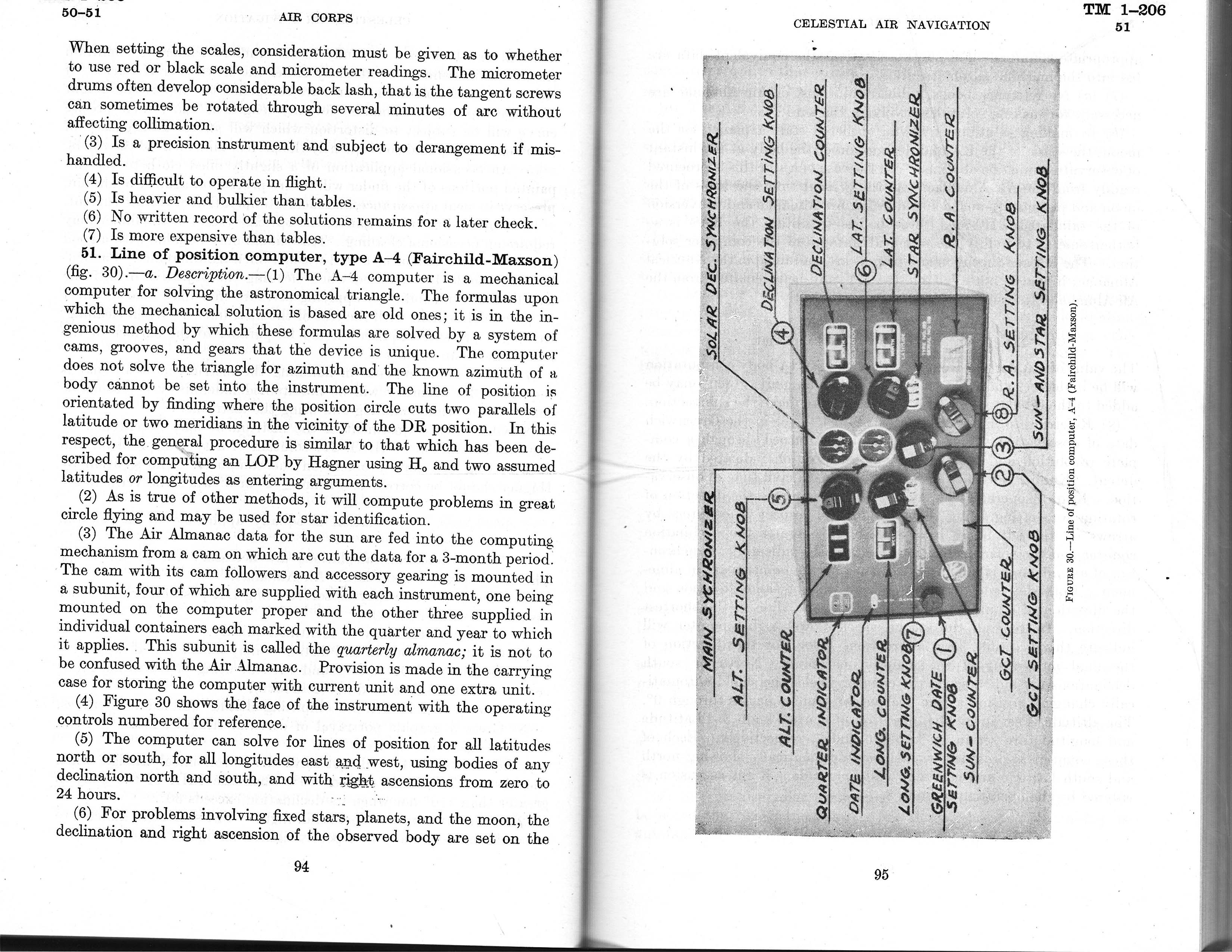

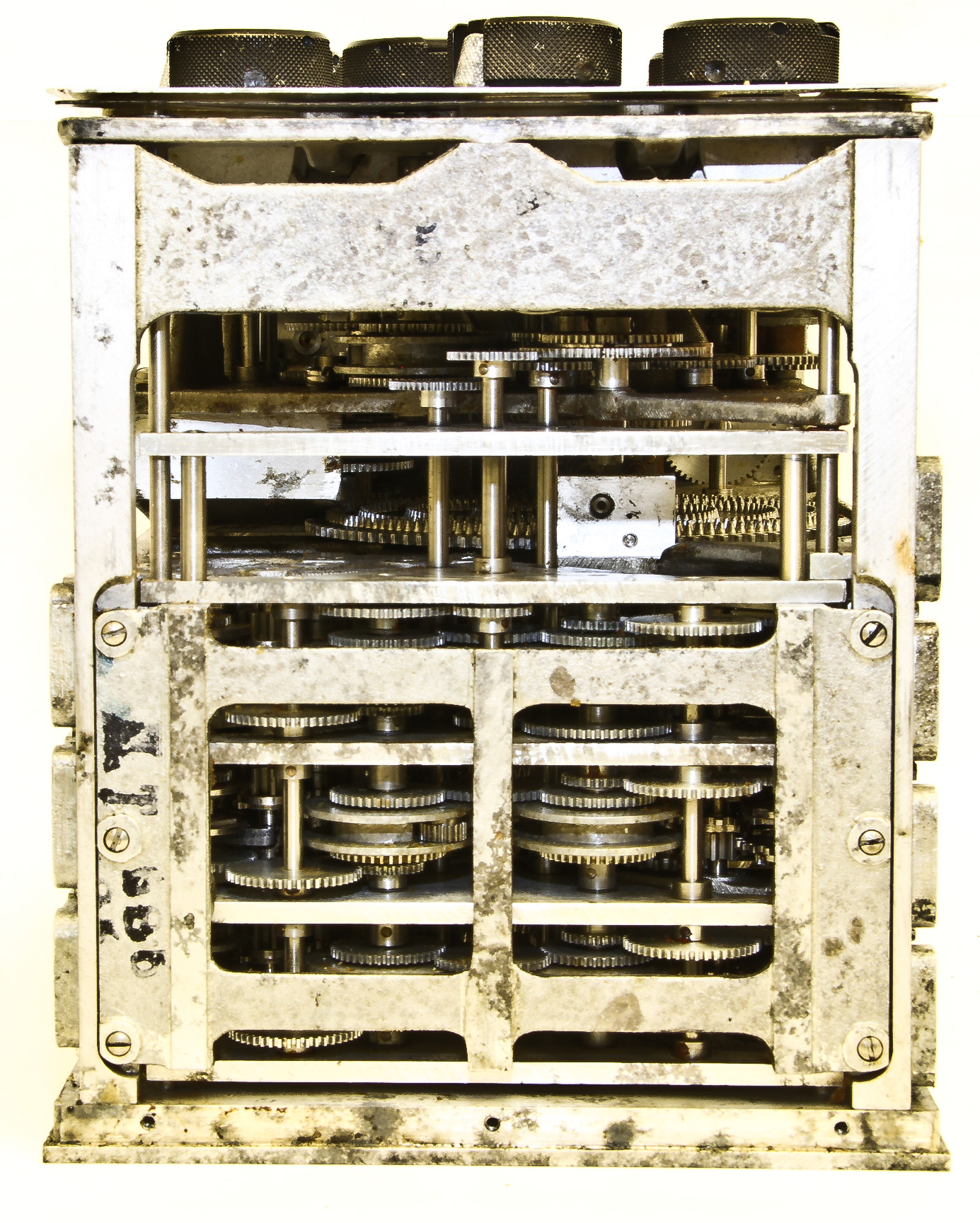
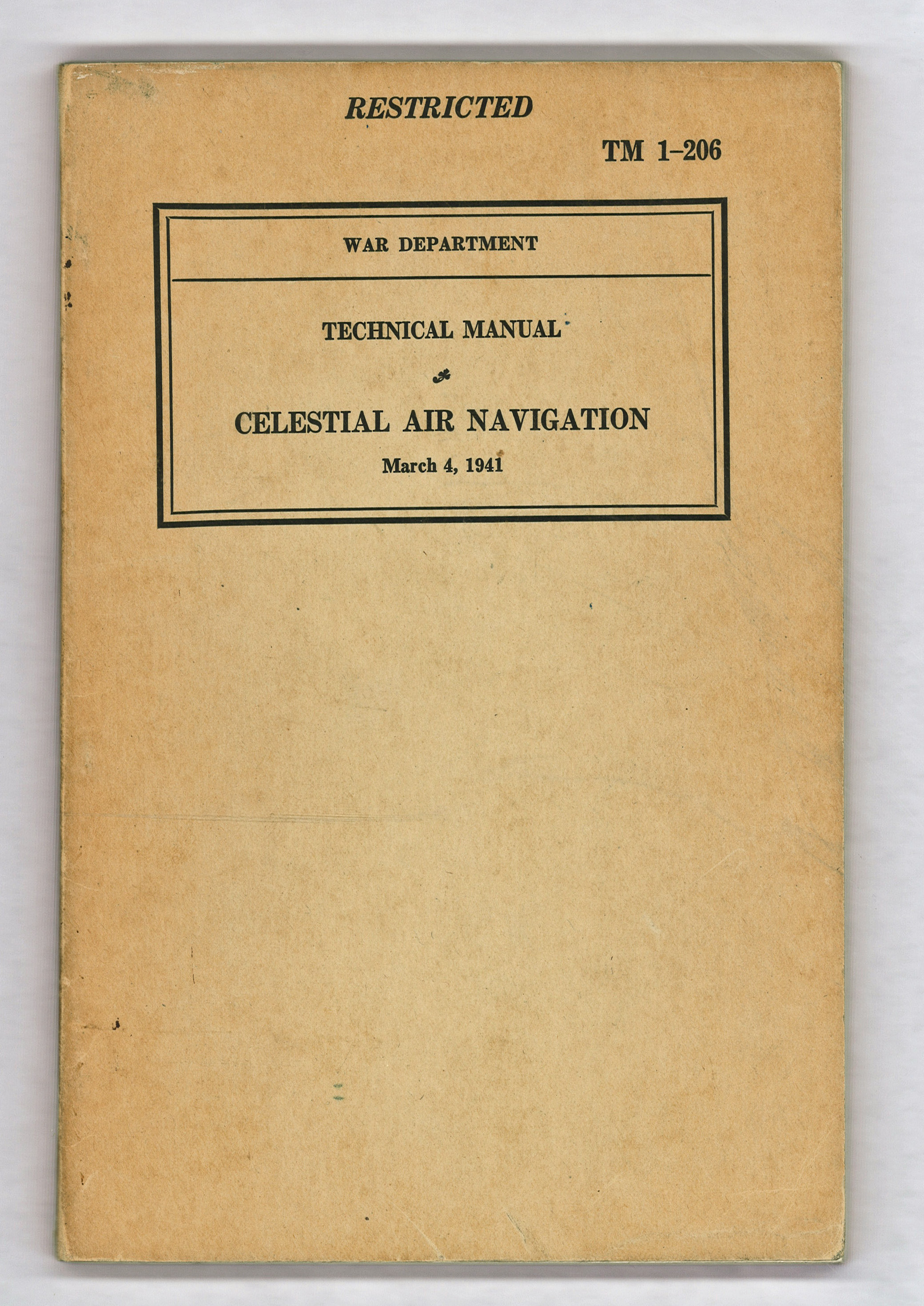
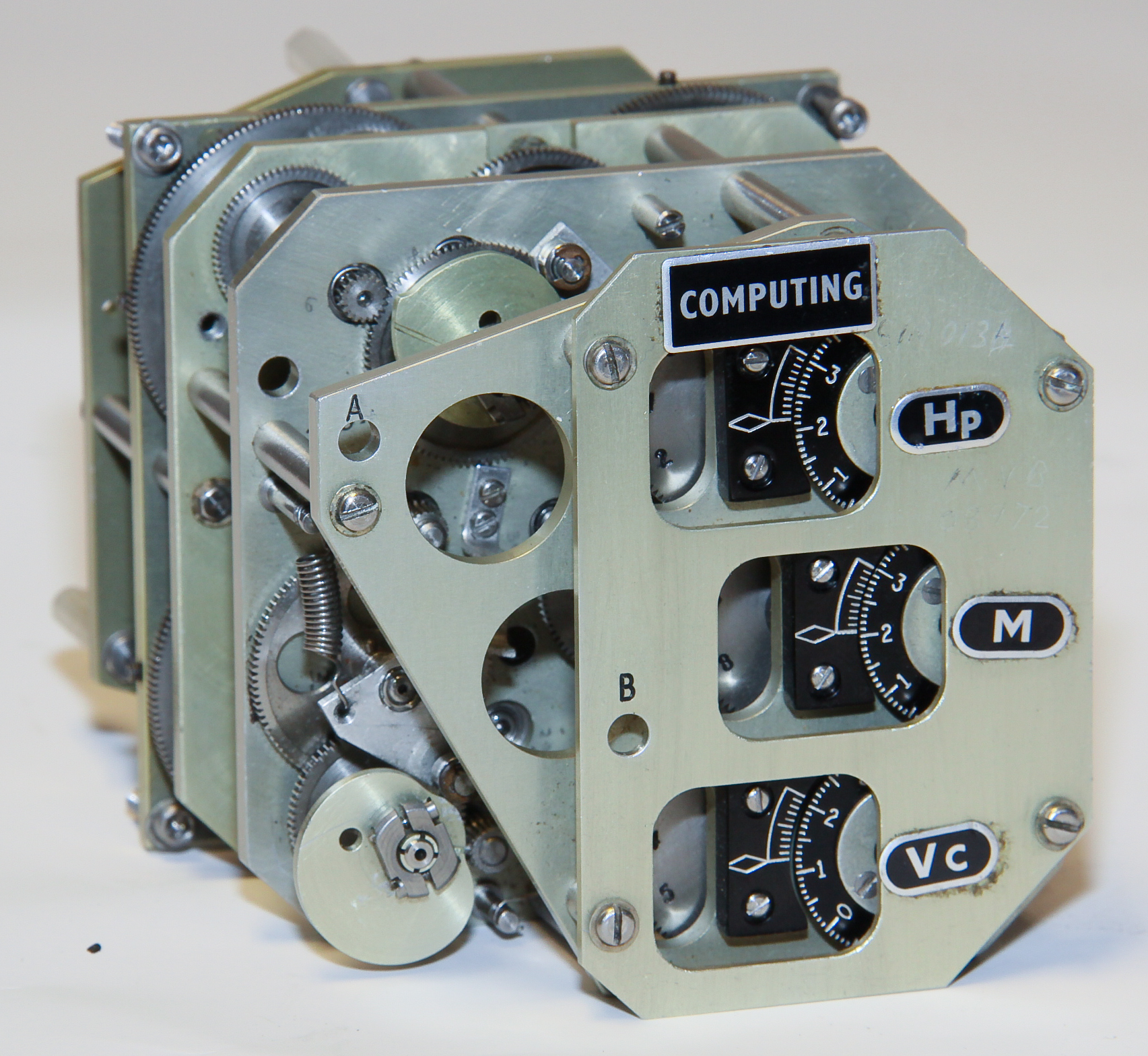
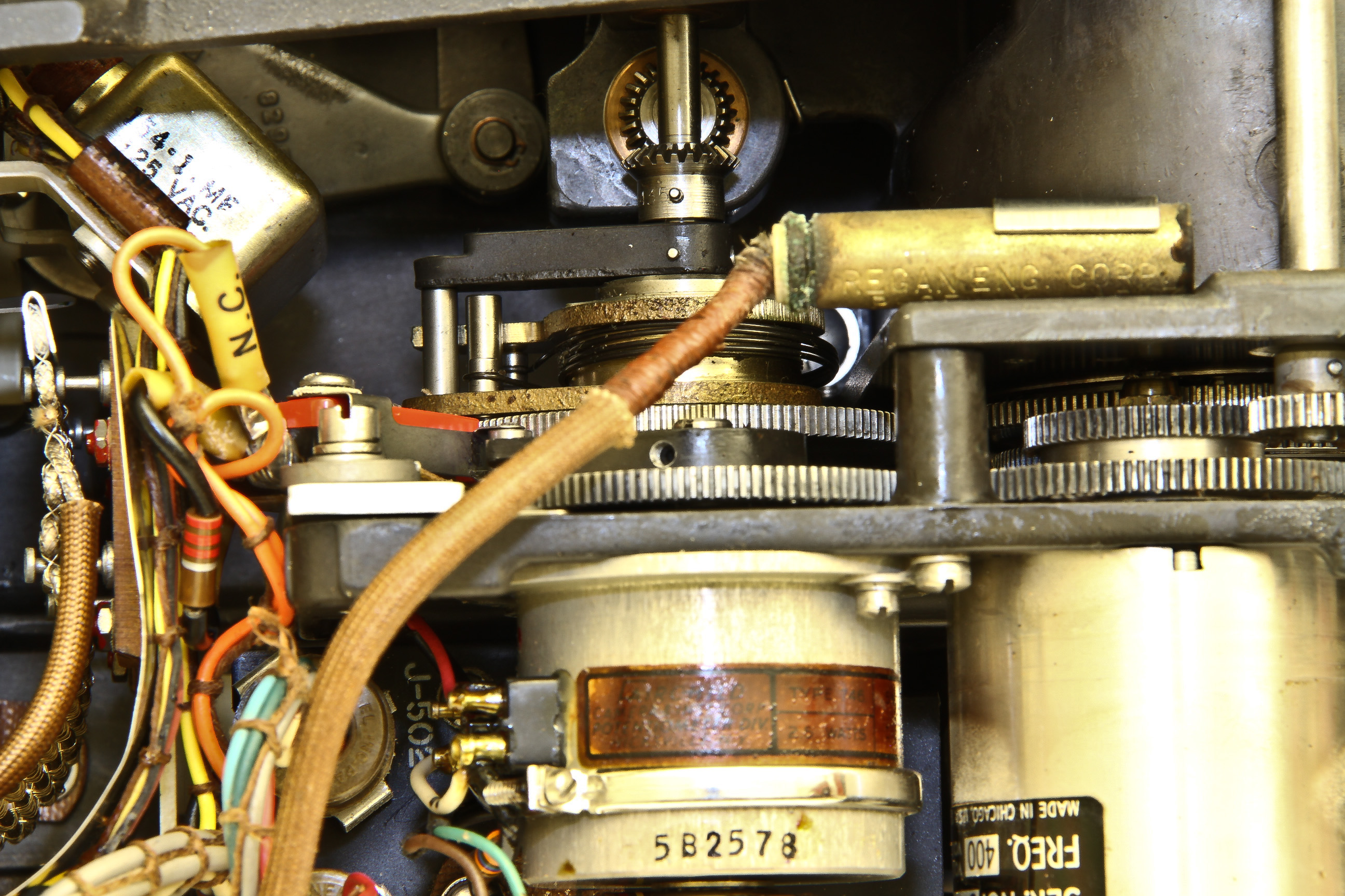
This wonderful device is a self-contained mechanical computer from the late 1930's that calculates a type of celestial navigation called "line of position". (If you're not fluent in celestial navigation, it more complicated than one might think. If you want to know more, there are many of good references on the web and here is a free book I recommend.) Another great reference is Technical Manual TM1-206, 1941 (Figure 12) which includes a description of how to use the A-4 computer (Figure 13).
A very simplified description of line-of-position navigation is that given the time of day and sighting data (from a sextant) of the sun or another celestial body like a star, and by using precomputed tables, you can calculate the coordinates of a line on the surface of the earth, upon which you must be. Two such sightings and calculations produce two lines, whose intersection is where you are. (Technically, these "lines" are not lines but are "circles of equal altitude" which intersect at two positions, but in practice the position is not ambiguous.) The line of position approach was discovered in 1837 by Thomas Sumner (his original publication describing the method is here)
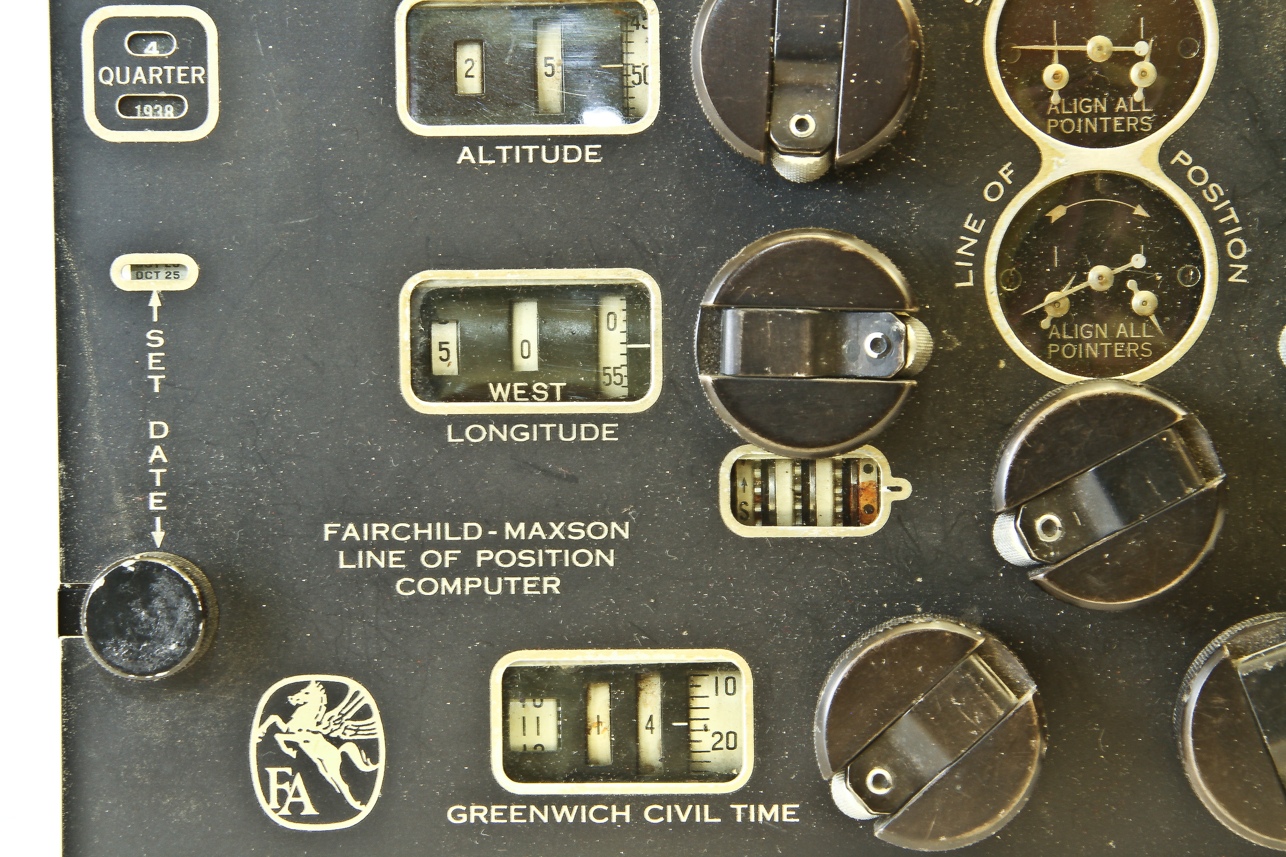
Although celestial navigation from a ship and an airplane are conceptually similar, there are important differences, among these are the fact that airplanes lack a stable horizon, experience high acceleration, and rapidly change their position. This means that it is important to be able to make position estimates accurately and rapidly. Before the A-4 computer, the line of position calculations required solving several trigonometric formulas using data from massive celestial almanacs. These calculations were done by hand or using specialized slide rules. The A-4 performs these calculations with greater precision than slide rules, and most conveniently, has the almanac values for the sun built into it, thus eliminating almanac lookup in many cases.
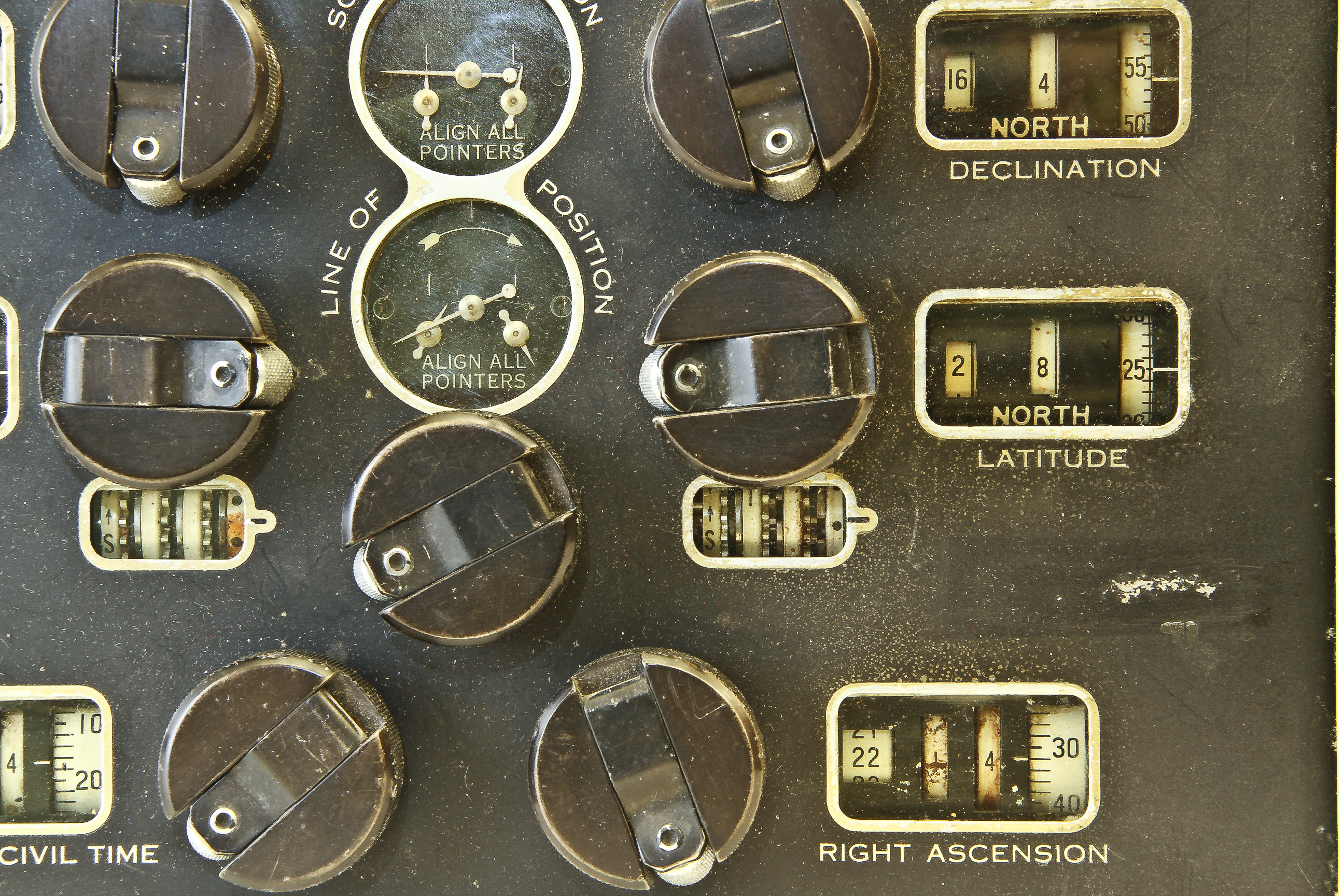
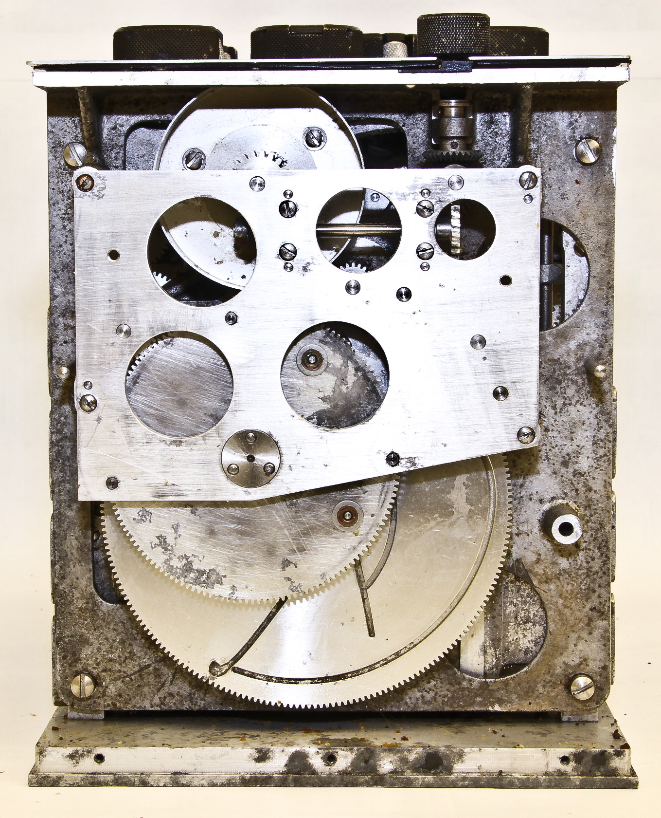
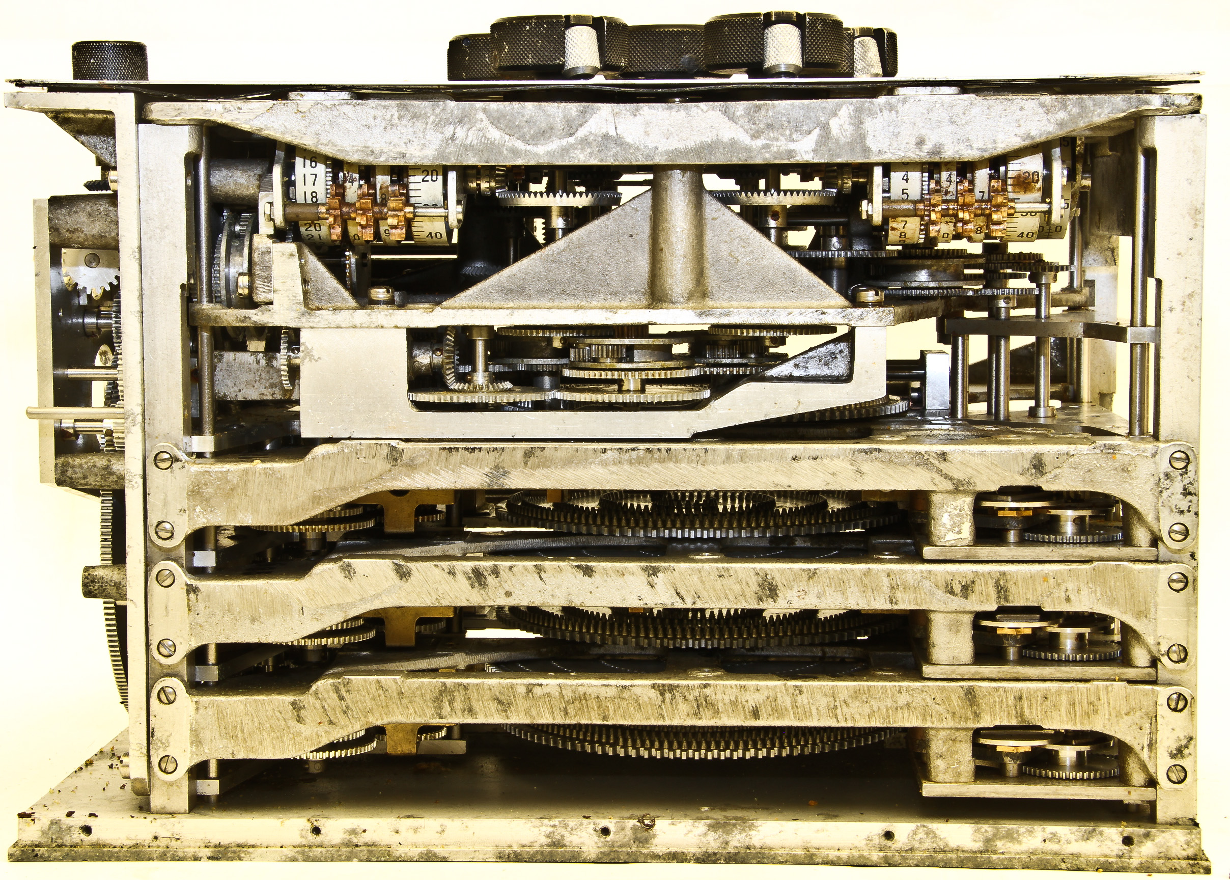
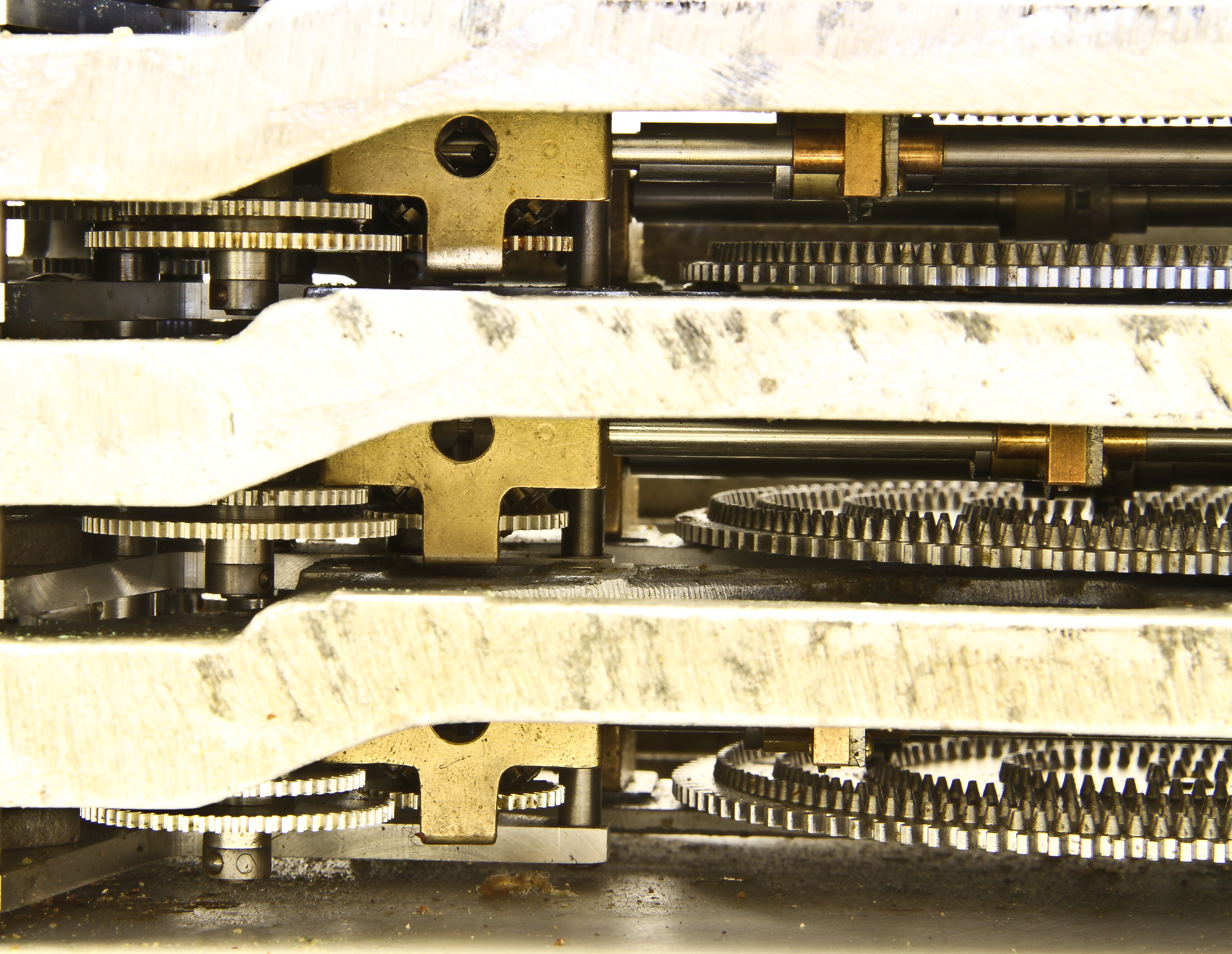
As can be seen in Figures 6-10, the computation mechanisms are completely mechanical and are quite complicated.
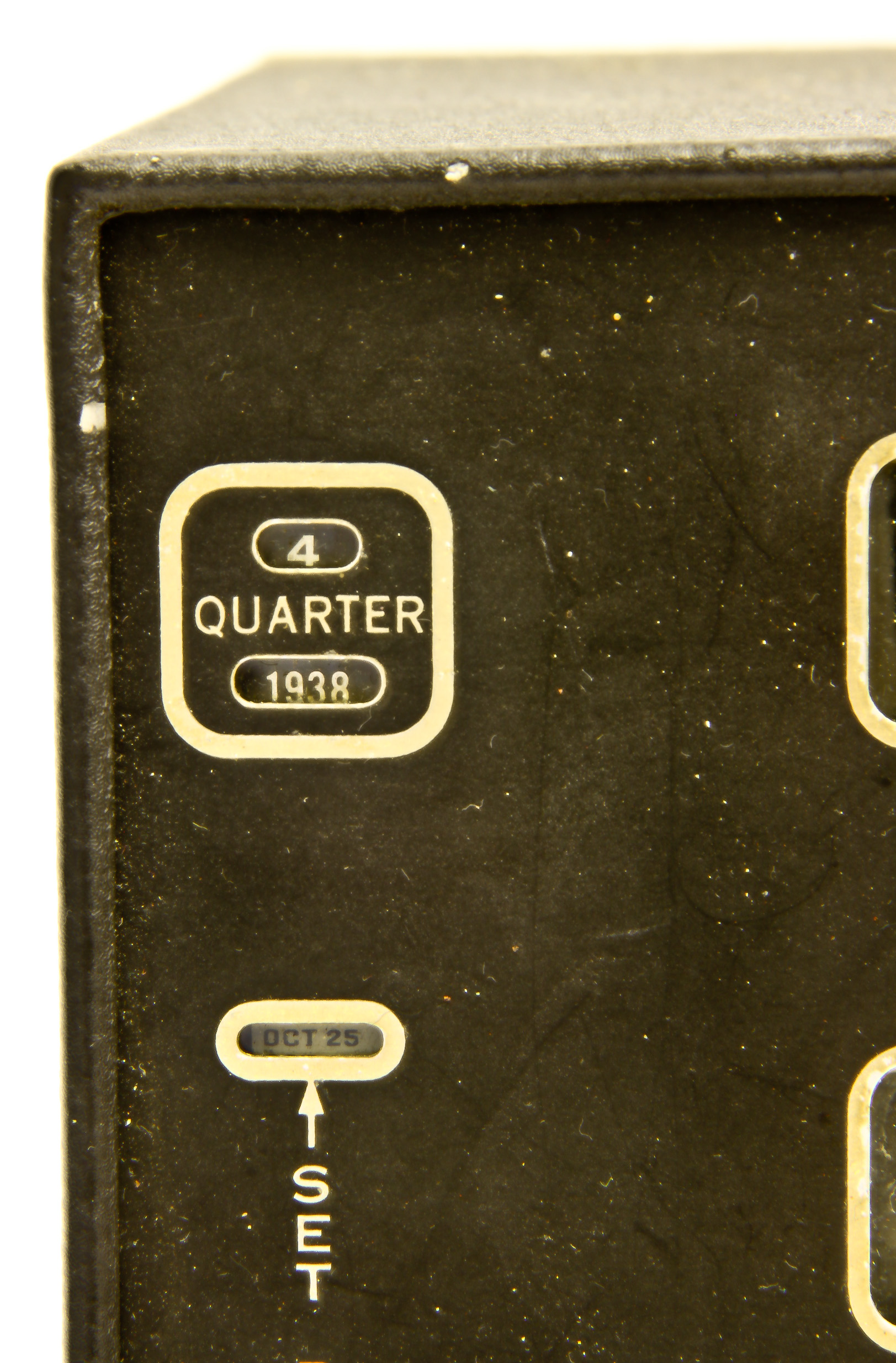
The astronomical almanac data for the sun is machined into a replaceable module that covers a particular quarter of a year. Our data is for fourth quarter, 1938 (Figure 5). The replaceable unit is the shiny mechanism in Figure 9. Close examination show part of a large gear with a track cut in it. This is the data.
An interesting historical note: the Fairchild A-4 was used by Howard Hughes of his flight around the world in 1938.
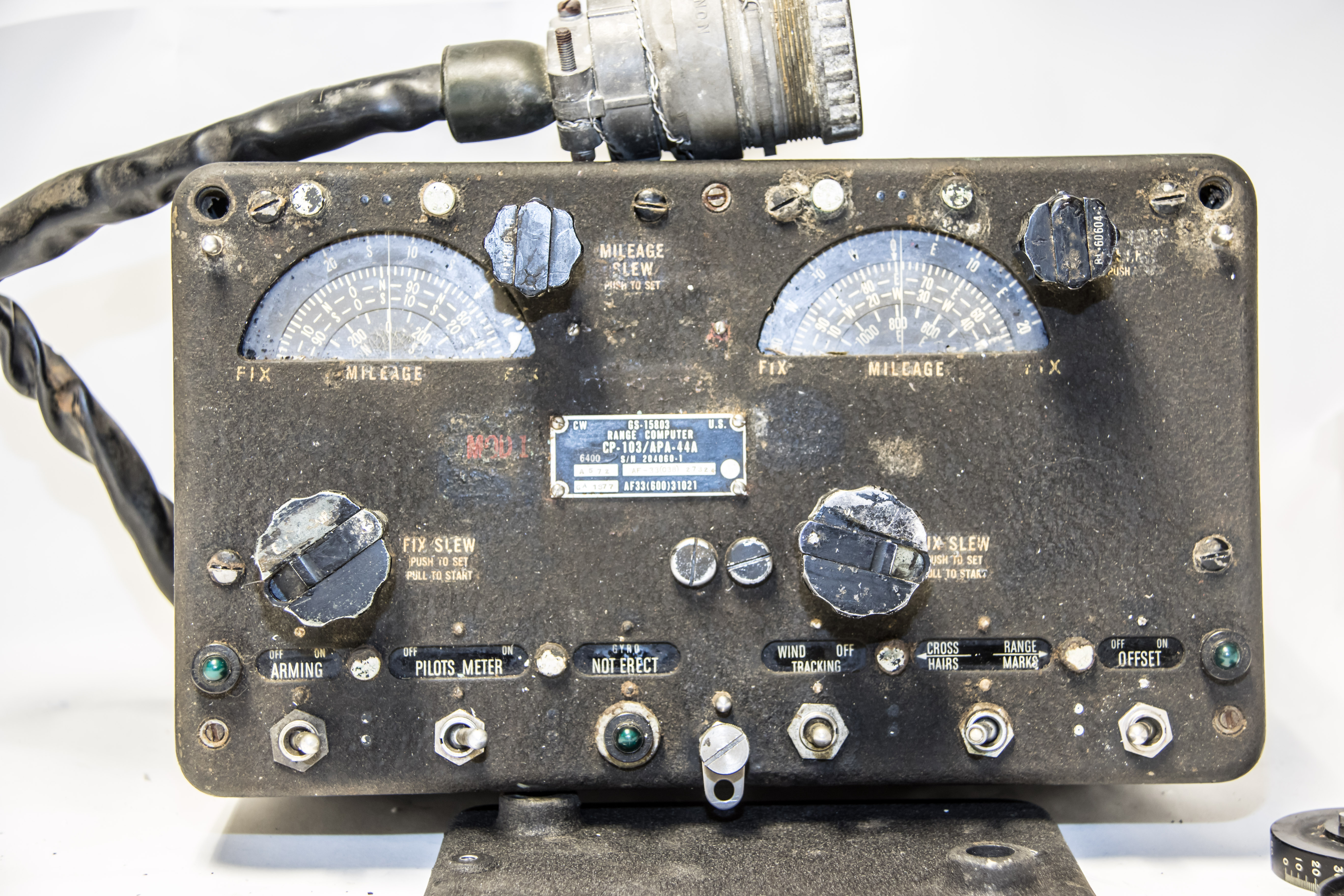
I don't know much about this device other than the AN description:
AN/APA-44: Ground Position Indicator System; manufactured by Bell Telephone Lab.; used with AN/ASB-3 and AN/APS-23/27/31; used in B-45 (together with AN/APS-23 to form AN/APQ-24), RB-66
where ASB-3 is:
AN/ASB-3: Bomb Directing Set; manufactured by Bell Telephone Lab.; used AN/APA-44, AN/APS-23
and the APS- devices are search radars. And:
AN/APQ-24: K-1 Radar Navigation & Bombing System; used in B-36B, B-45A, B-50, B-66B
The fact that this device was used on the B-45 Tornado bomber is interesting. The B-45 was U.S.'s first jet powered bomber and the first with in-air refueling. It looked suspiciously like a World War II bomber with jet engines instead of propellers. For example, the wings were staright instead of swept back.
The B-45 is not well known today since it was limited in many areas and was fairly quickly replaced by the B-47 Stratojet bomber, the first bomber with a modern jet-based design. There were only 143 B-45's produced and they entered service in 1948 and by the early 1950's, most had been converted to reconnaissance versions, the RB-45.
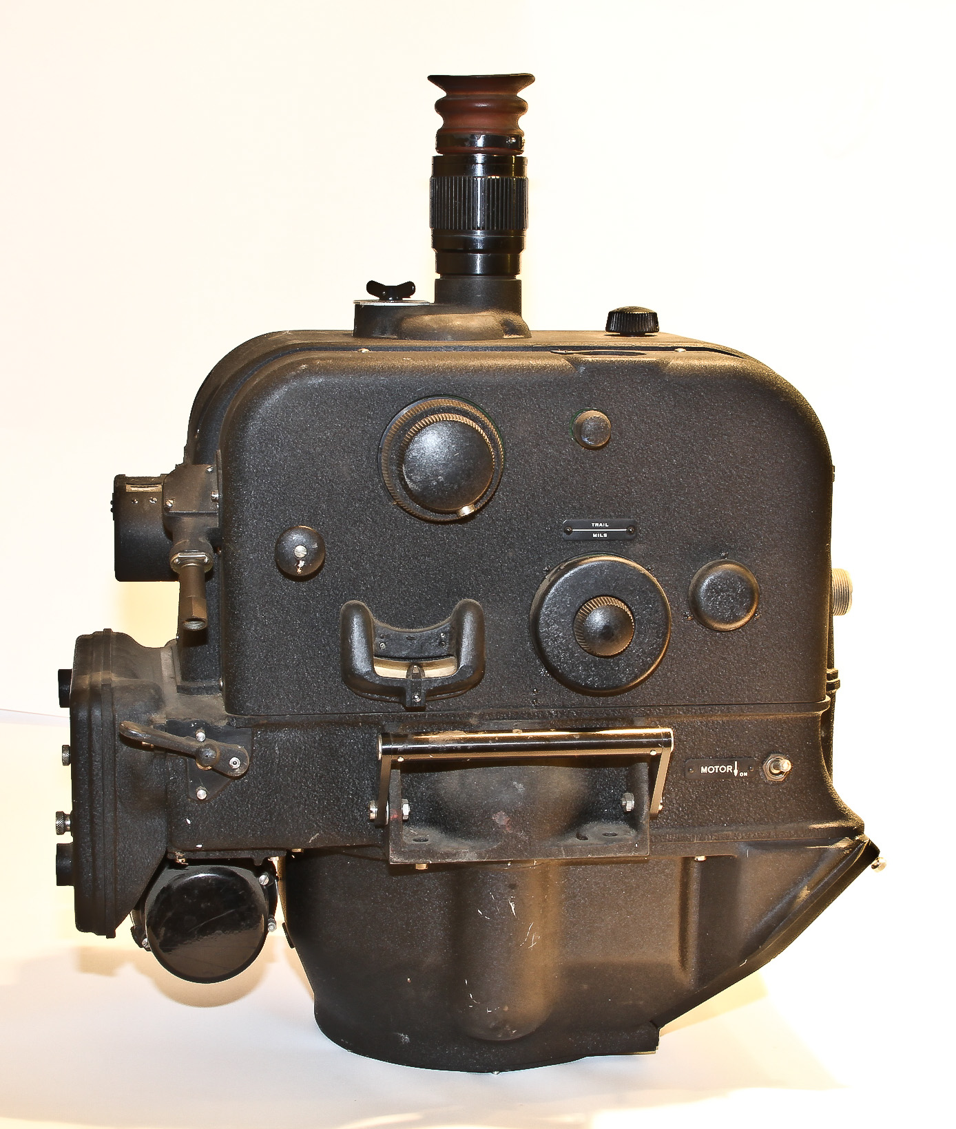
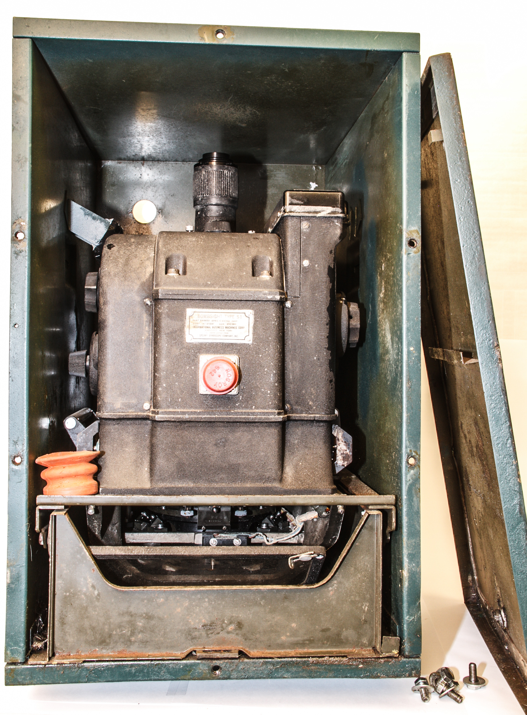
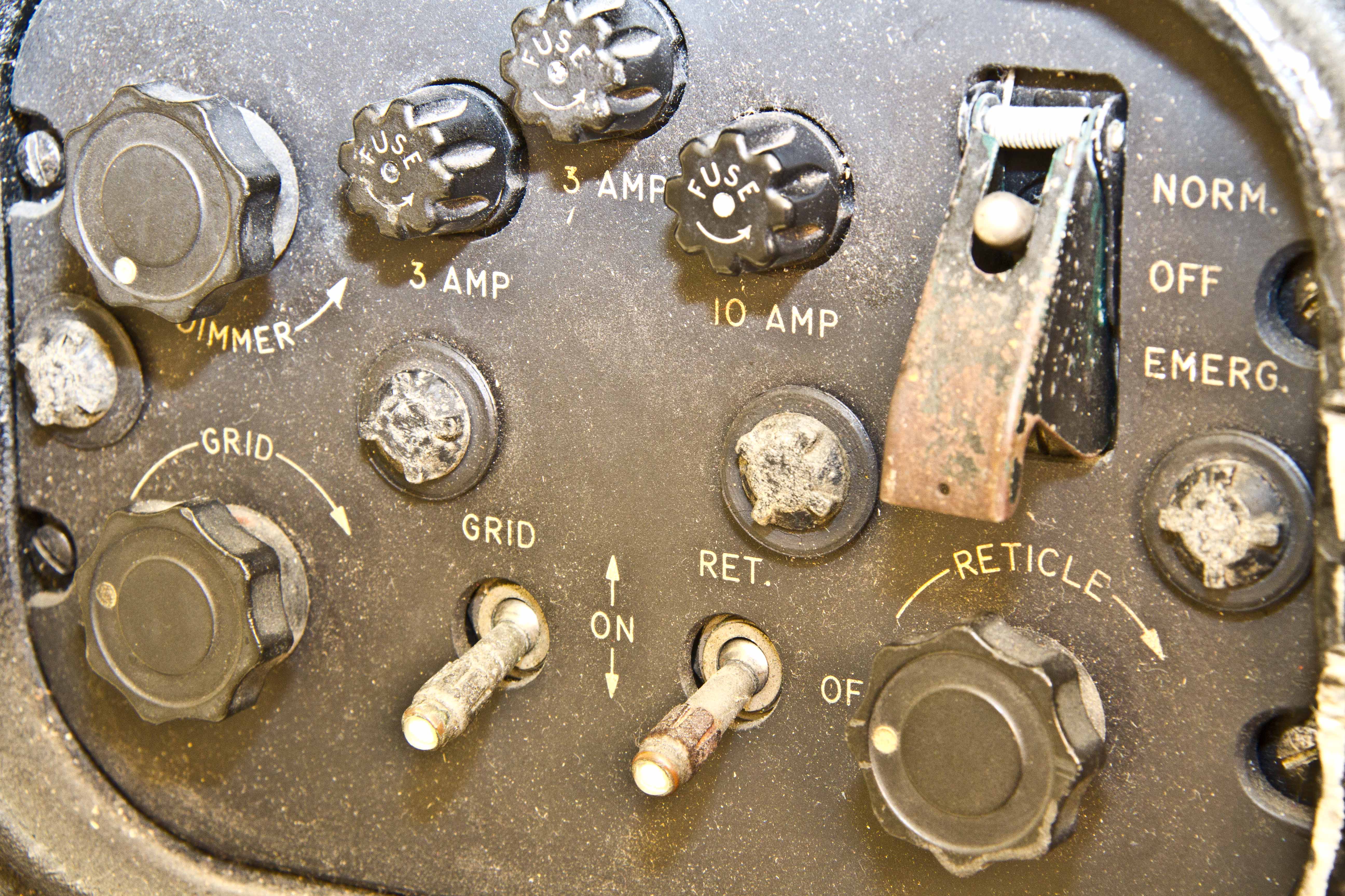
It turns out that the famous Norden bombsight was not only U.S. bombsight of World War II. The first bombsight accepted by the Government was the Sperry S-1 that was developed in the 1930's. It was designated as "standard" equipment in March 1941 and was used in some U.S. Army Air Forces bombers early in World War II, primarily B-24 Liberators. However, all contracts for production of the Sperry sight were canceled in late 1943. Many claim that the Sperry S-1 was a superior design to the Norden and clearly politics were involved in the procurement decisions. The September 1999 issue of IEEE Spectrum has a very good article on this topic, appropriately called The Bombsight war: Norden vs. Sperry.
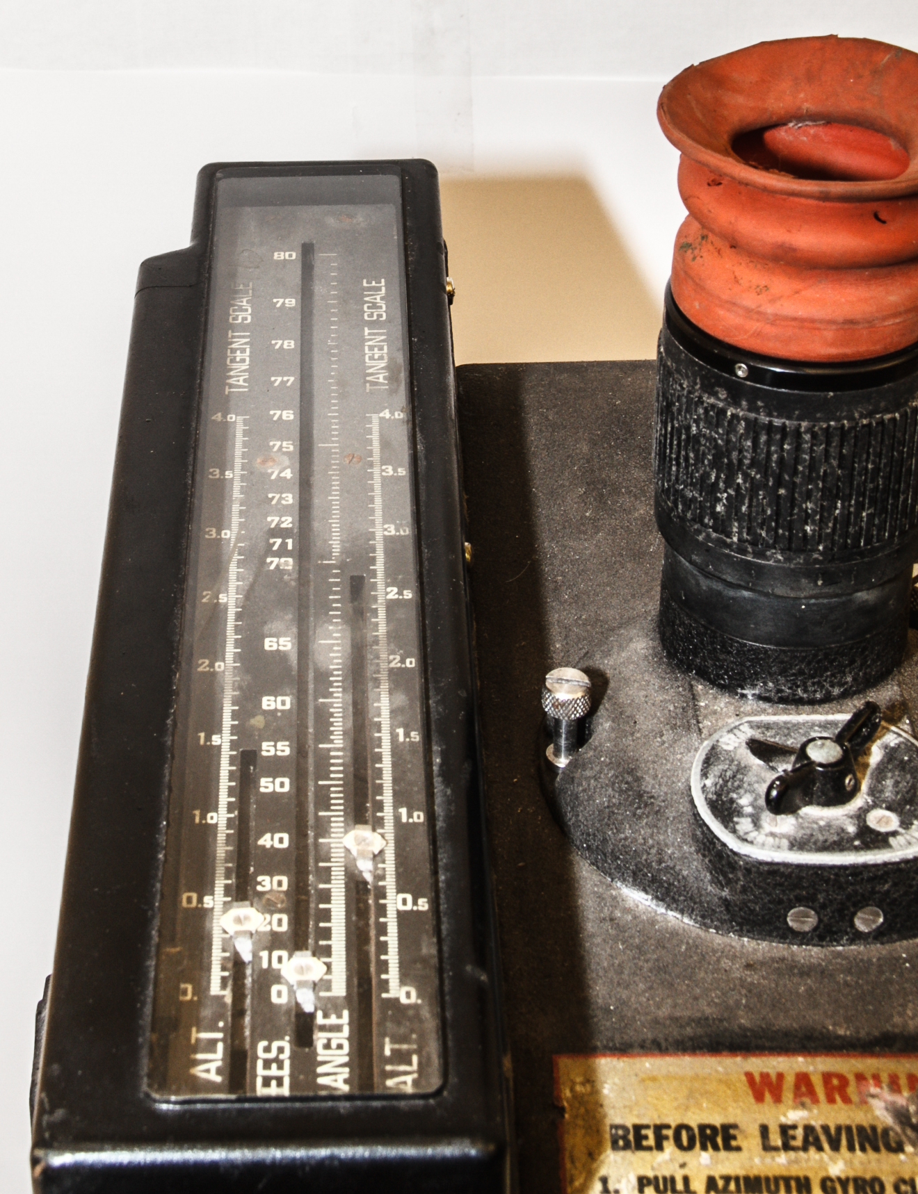
As shown in Figures 1 and 2, the Sperry S-l sight is essentially a cube with control (data input) knobs on each side and a vertically mounted telescopic viewing system. (Figure 2 shows the fact that we just acquired another S-1; see discussion of it below). The data input knobs are similar to the Norden bombsight, but were positioned on both sides of the instrument. Primary controls on the right side were concentric azimuth rate and displacement knobs, a cross-trail correction knob, a trail knob for setting in the standard value for the bomb, and a caging control for the vertical gyro. On the sight's left side were the concentric range displacement and rate knobs, a time-of-fall knob for setting in this bombing table datum, an angle sweep knob for initial location of target, and a caging control for the azimuth gyro. In Figure 1, the slanted portion at the bottom of the front is the viewing port of the telescope.
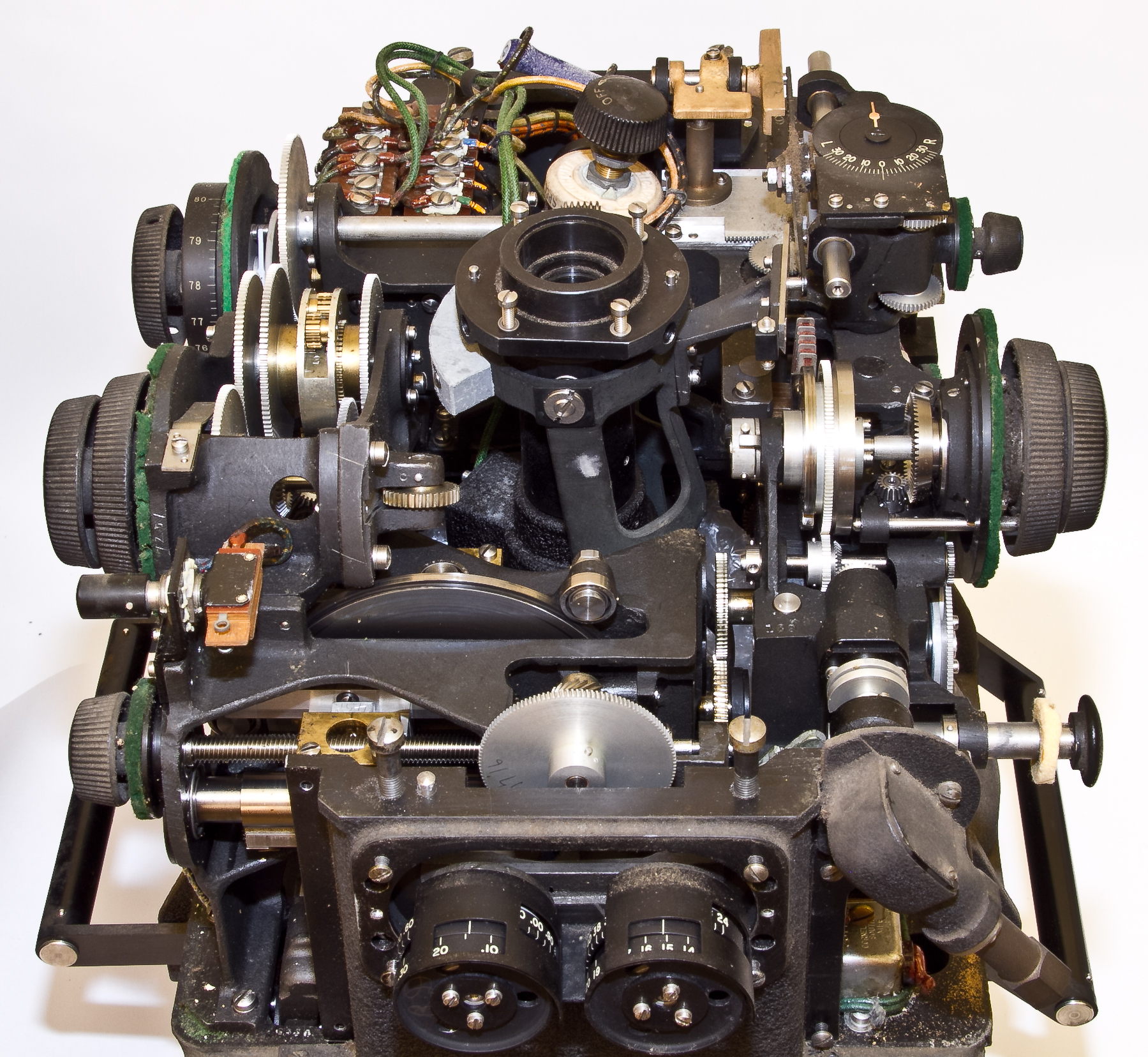
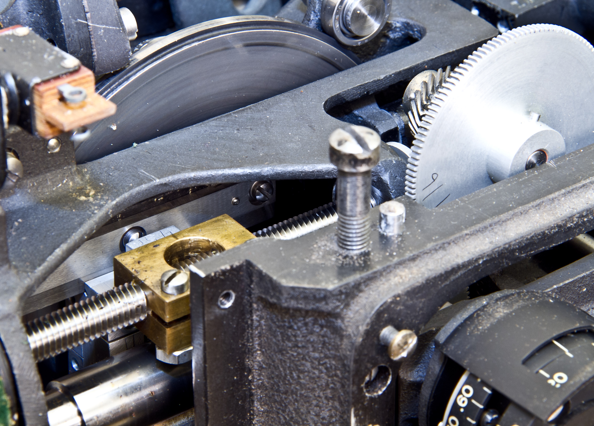
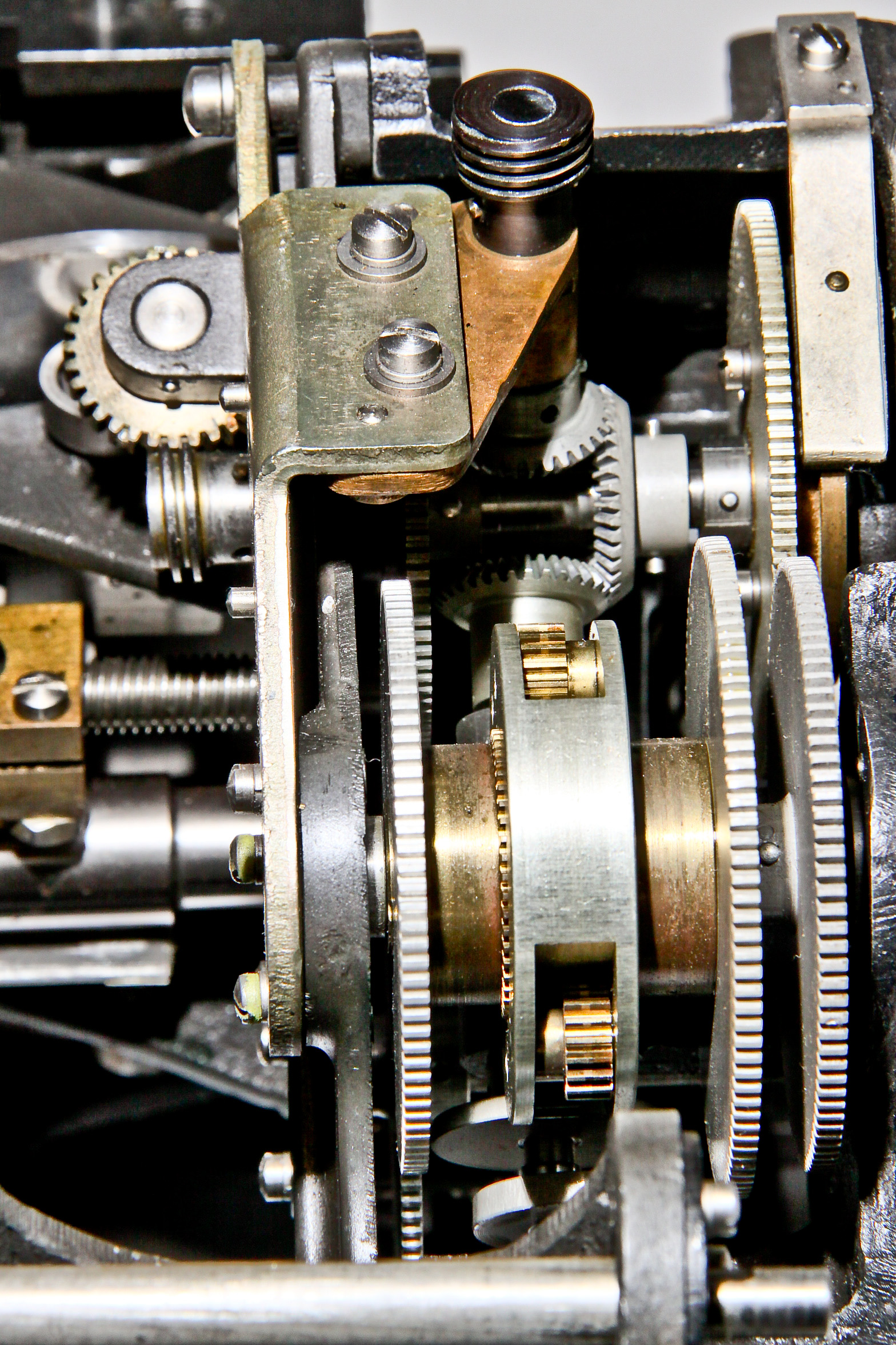
Figures 3,4 and 5 show some of the complicated mechanicals inside the S-1. It is hard to see, but Figure 5 shows the front of a disc integrator. The rotating disc in seen sticking up above the mechanism at the rear and the brass component is part of the mechanism that adjusts along the radius of the disc.
New news 3/2013: Even though I already have 1+ S-1 bombsights (see below), I just got another one which has some interesting and new (to my collection) features:
New news 10/2010: my original S-1 arrived in many pieces and I had long planned to reassemble it but reality has set in (reality = I never will get around to this) so I've now acquired a complete S-1.
Original news: I have acquired a disassembled S-1 as shown in Figures 11 and 12.
Also, Figure 13 shows the control panel for an A-5 autopilot which was developed to go with the S-1 bombsight. The A-5 seems to be the first all-electric three-axis autopilot (using tubes, of course).
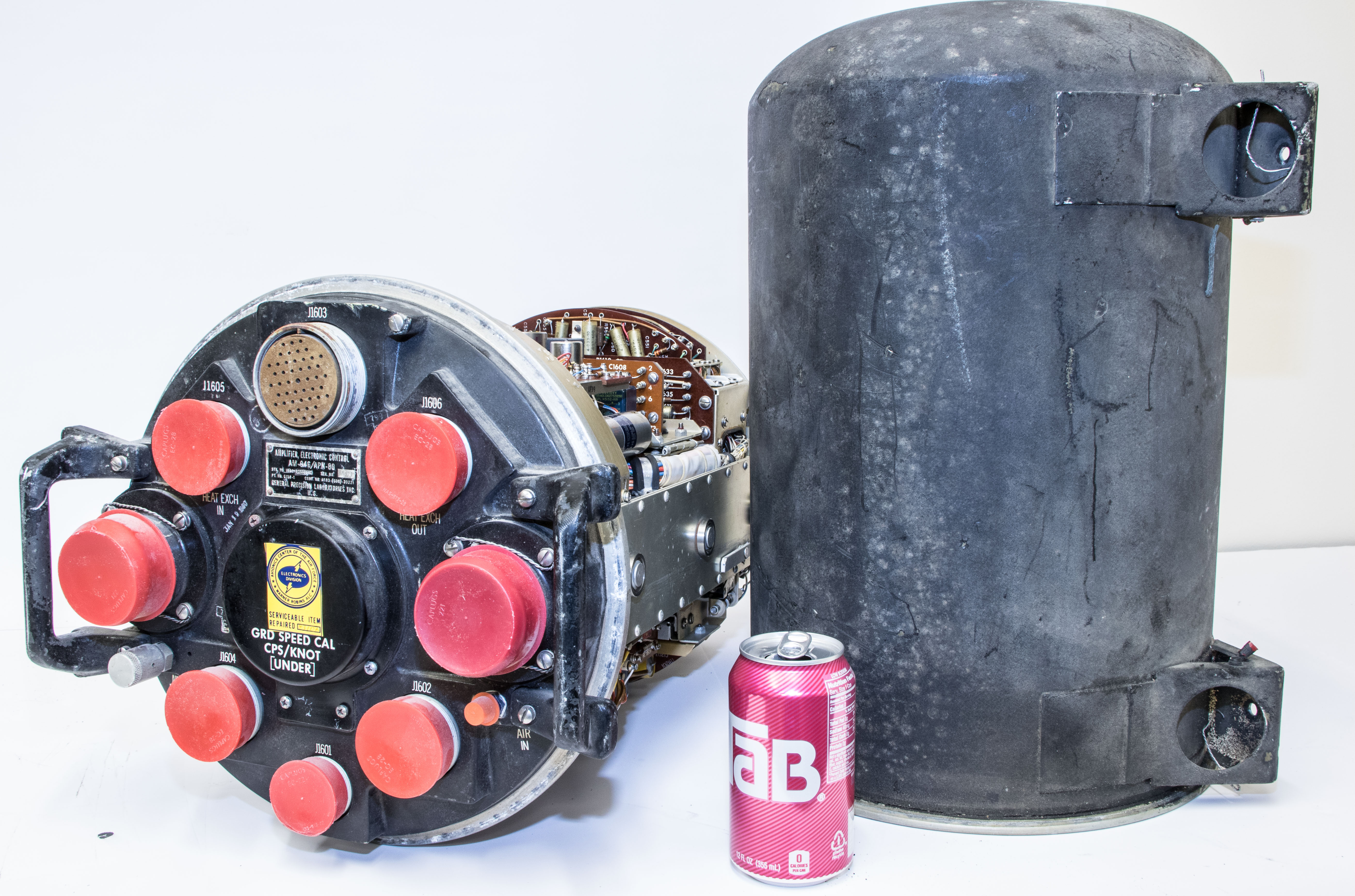
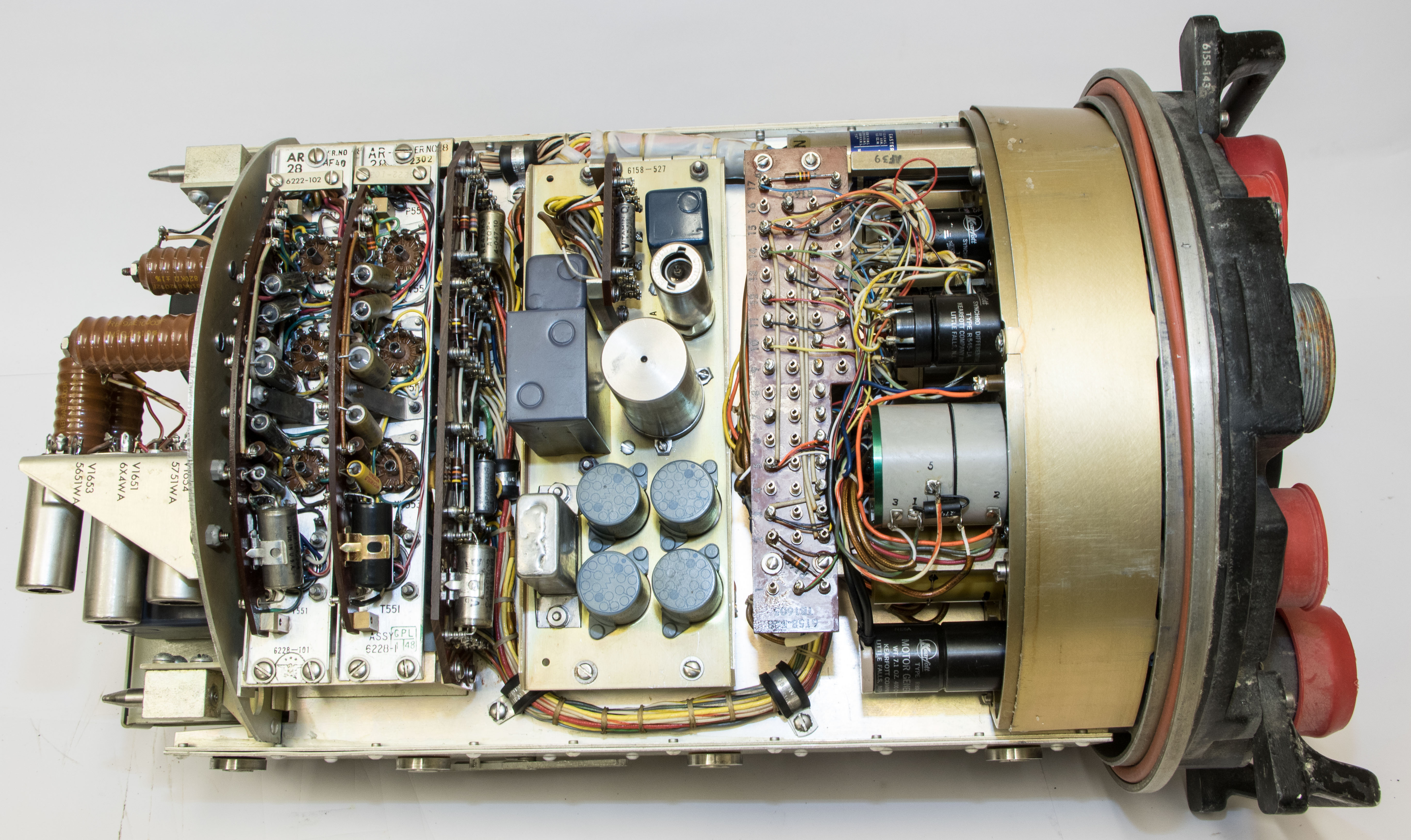
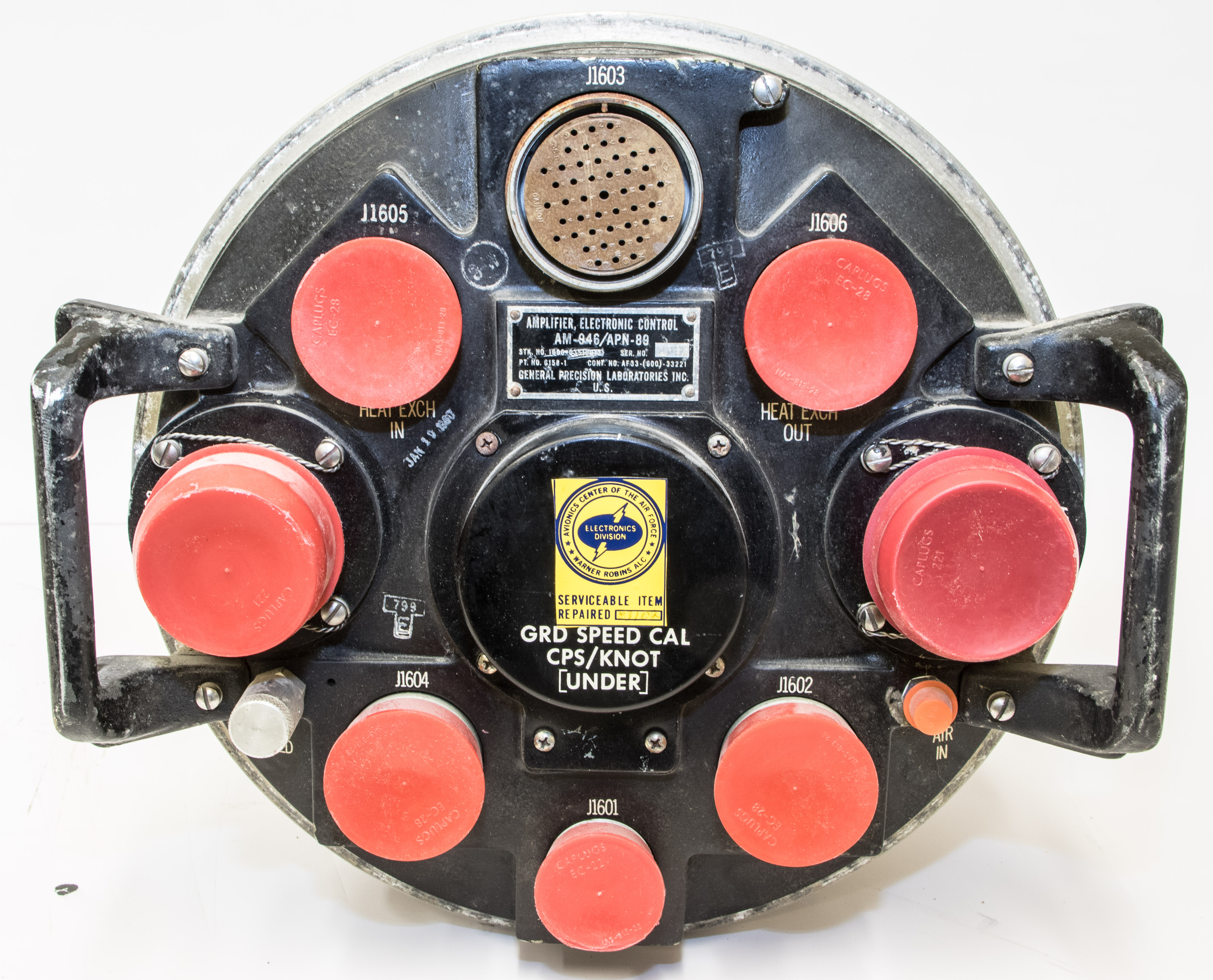
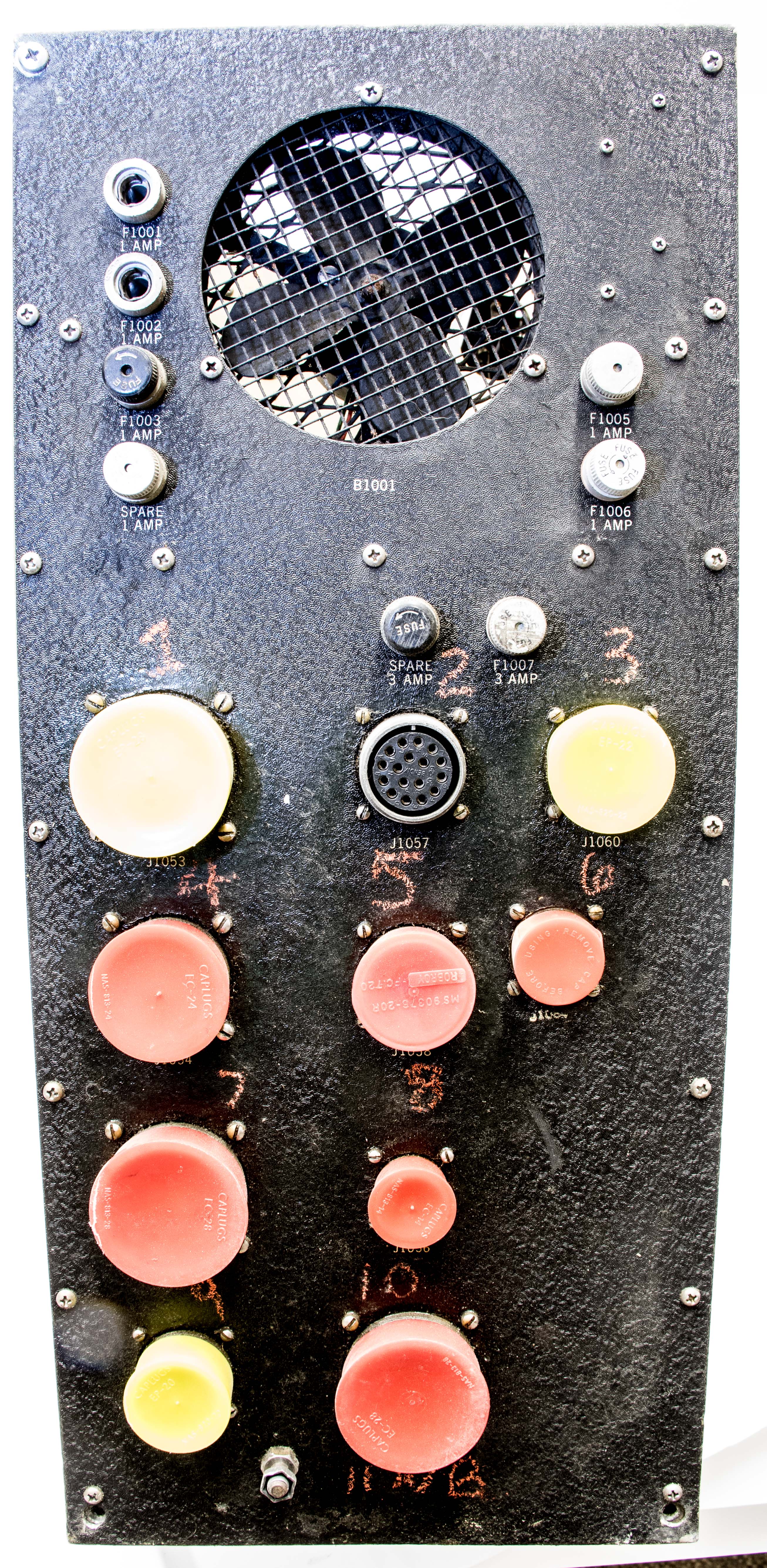
This device is one component of the AN/ASQ-38 bombing/navigation system developed for the B-52E bomber, first placed in service in 1957. The AN/ASQ-38 bombing and navigation system comprises many parts including:
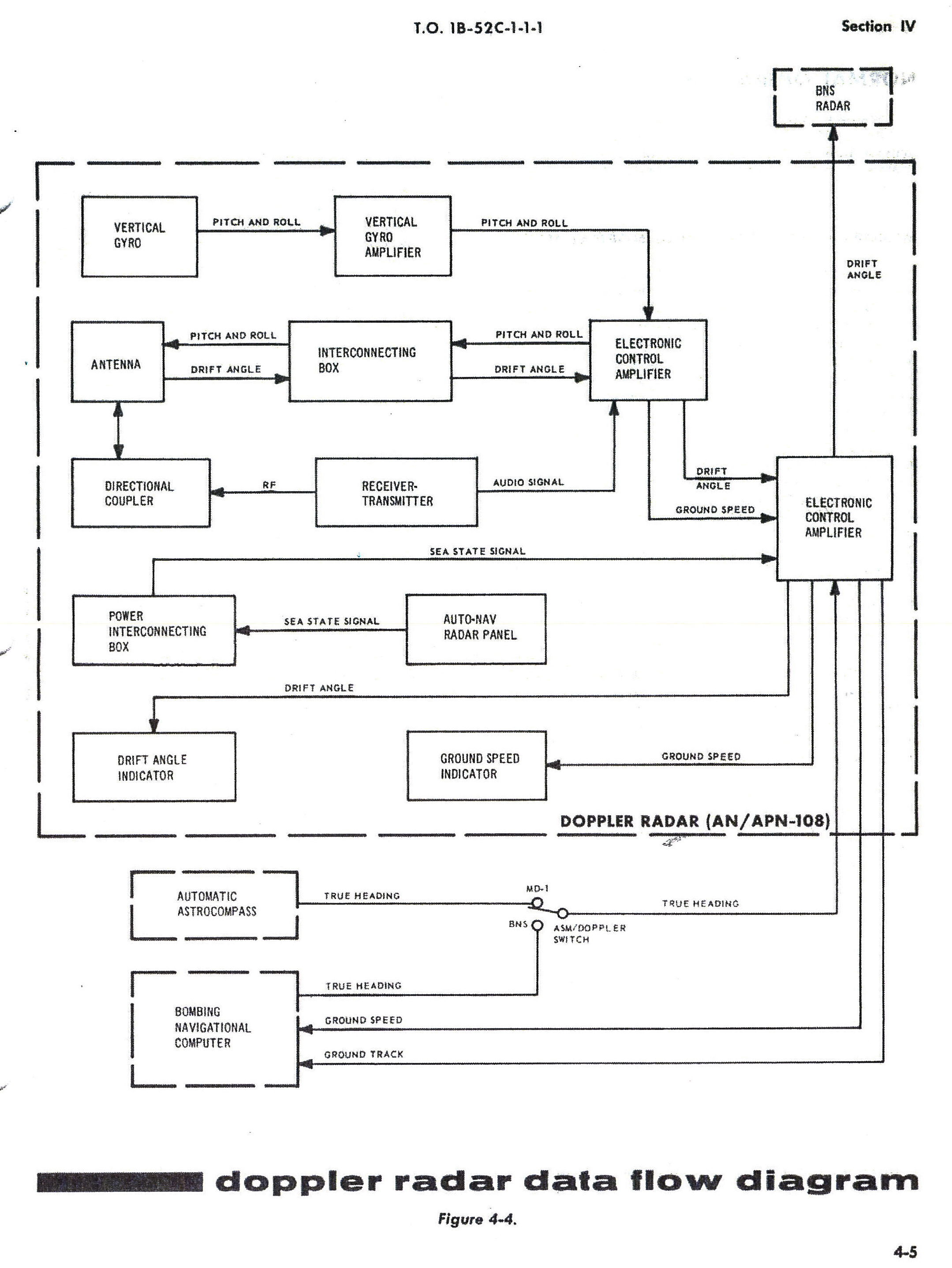
(Figure 6 shows the components from a very similar AN/APN-108, which was used on a different model of the B-52.)
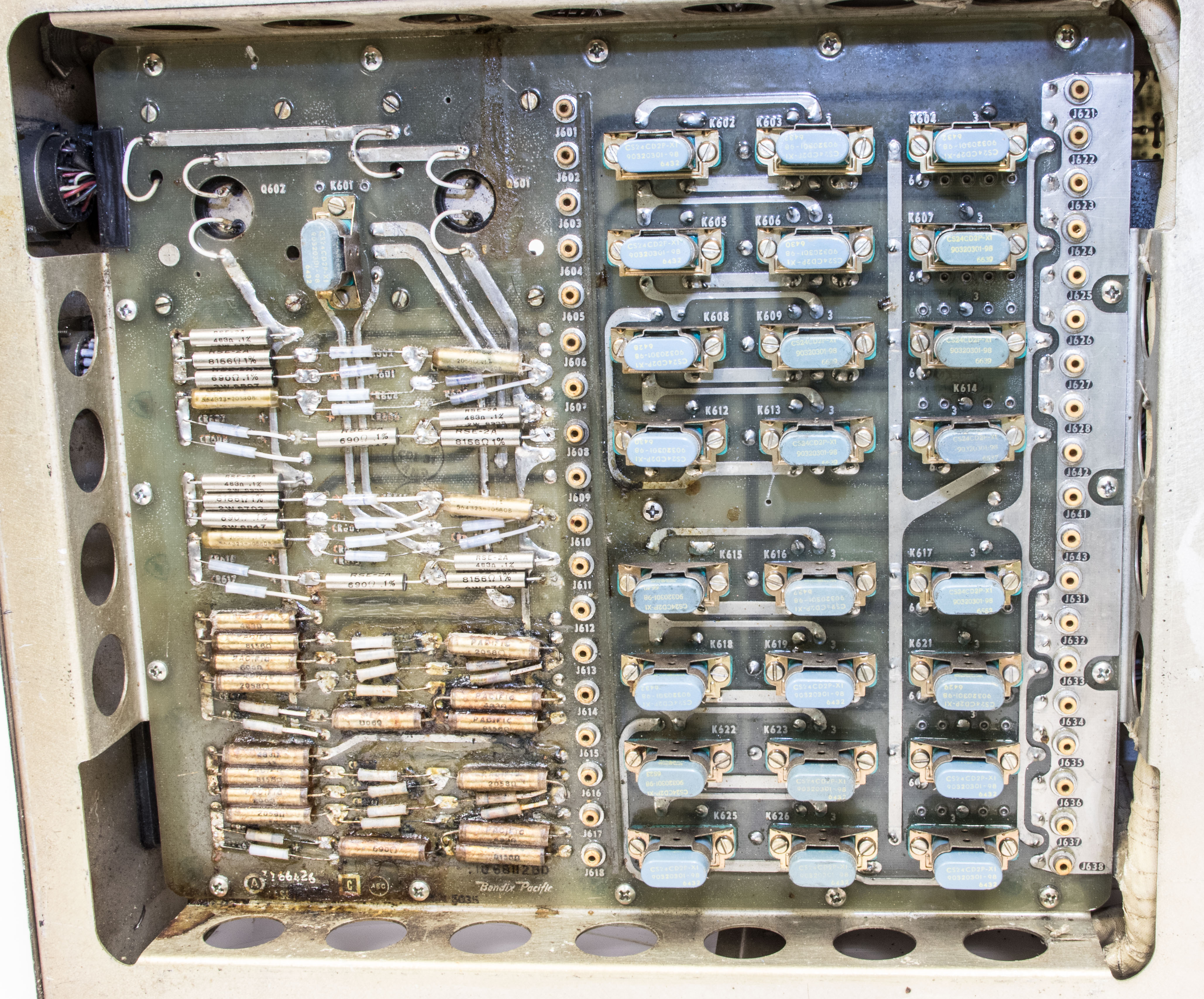
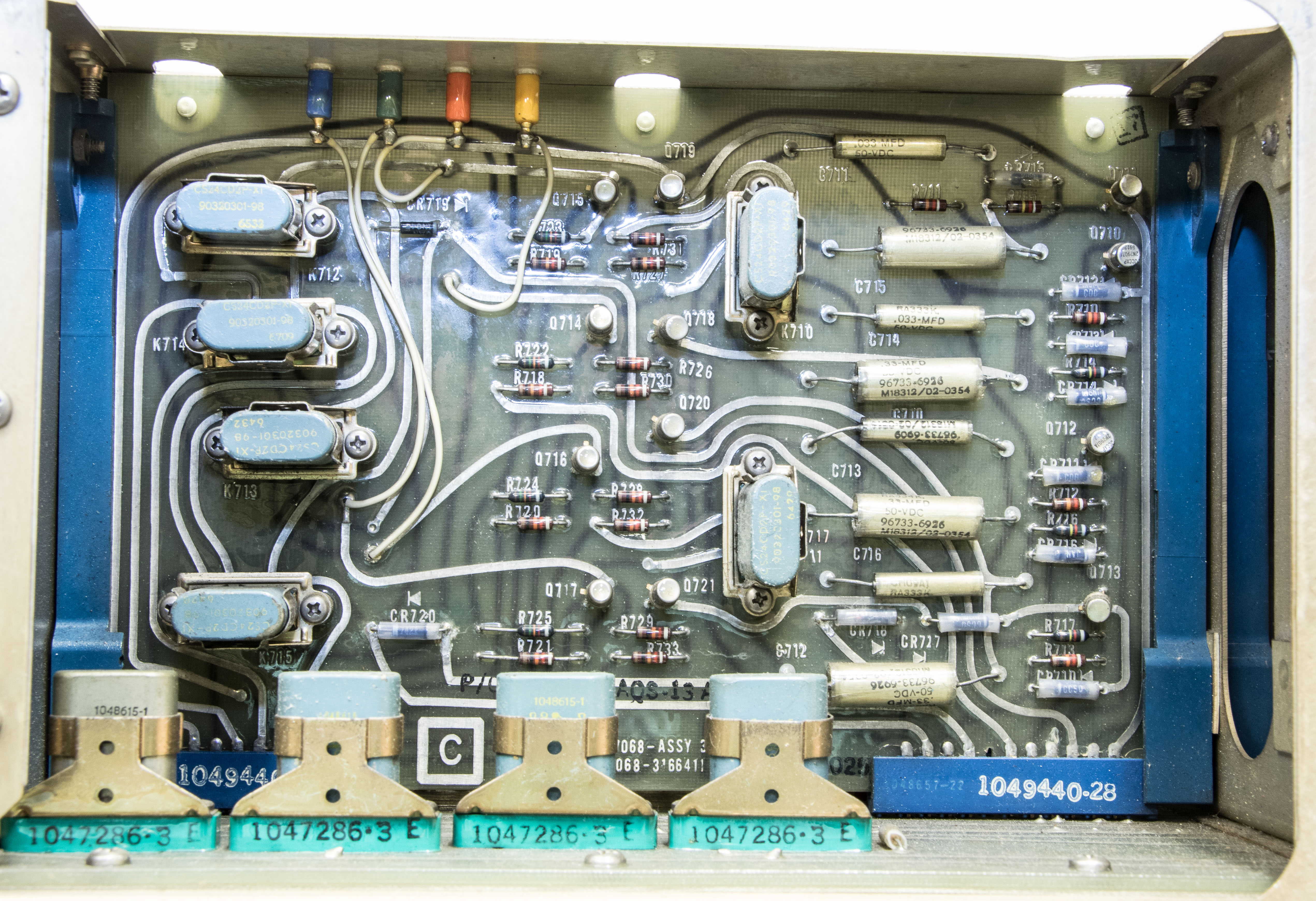
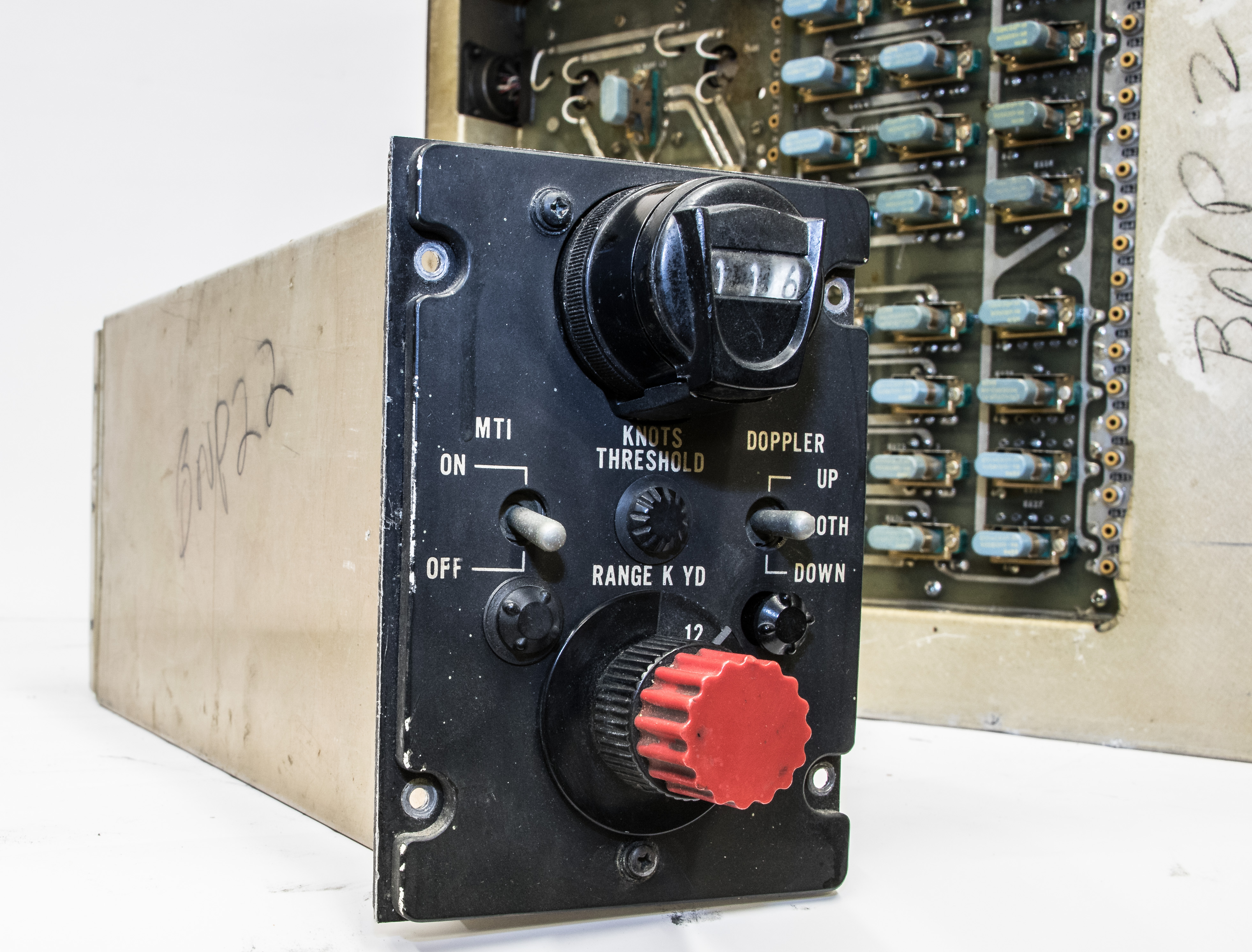
The APN-89 system uses doppler radar to provide ground speed and drift angle information to the ASb navigation system. The Doppler radar fed ground speed and drift information into the ASB navigation system. To calculate ground speed using Doppler radar, a radar signal is transmitted at a specific frequency that reflects off of the ground and returns to the plane. Since the plane's radar sensor is moving relative to the ground, the reflected signal will be shifted in frequency when it returns. This shift in frequency allows measurement of the relative velocity between the sensor and target. This, of course, is the same mechanism used in various speed detectors ("radar guns"), as well as in weather radar and many other applications.
The general formula for the shift in frequency is:
Fshift = 2V(Fi/c)cos(t)
where V is the velocity difference, Fi is the transmitted frequency, c is the speed of light, and t is the angle that the transmitted signal makes with the ground. Of course, this is only approximate since, for example, the radar beam spreads out causing a spead of returned frequencies (varying angles of intersection).
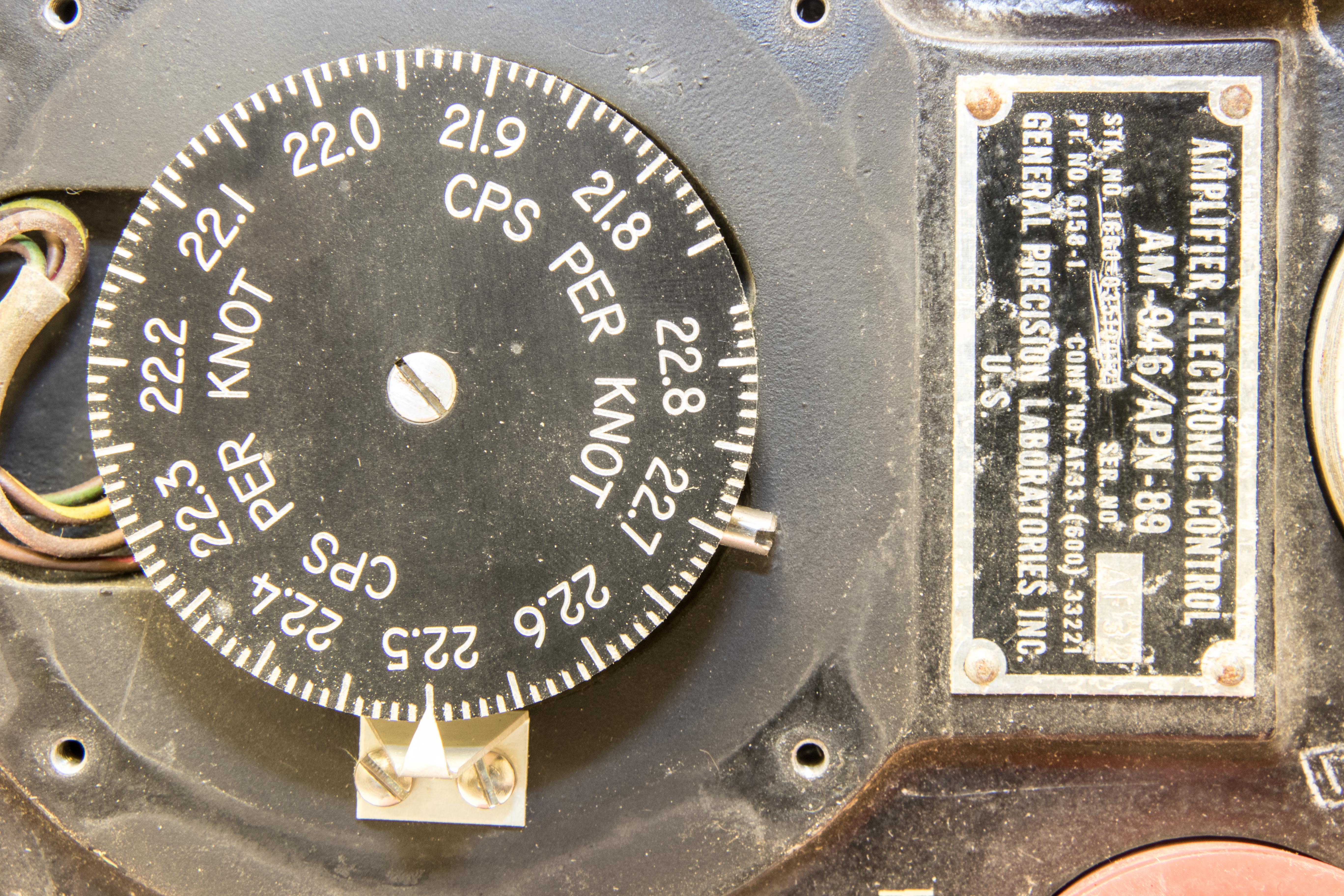
The APN-89 radar used a frequency of 8700-8900 MHz. The quoted accuracy was 2.1 knots and 0.15% drift angle.

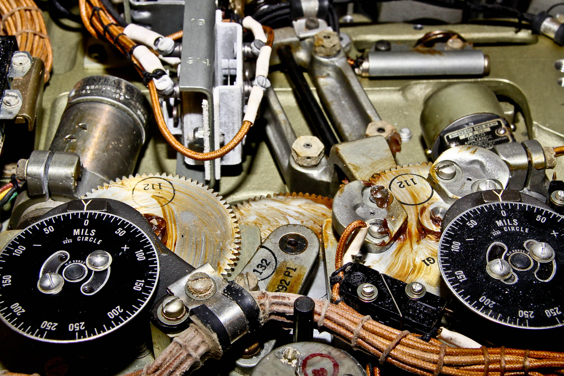
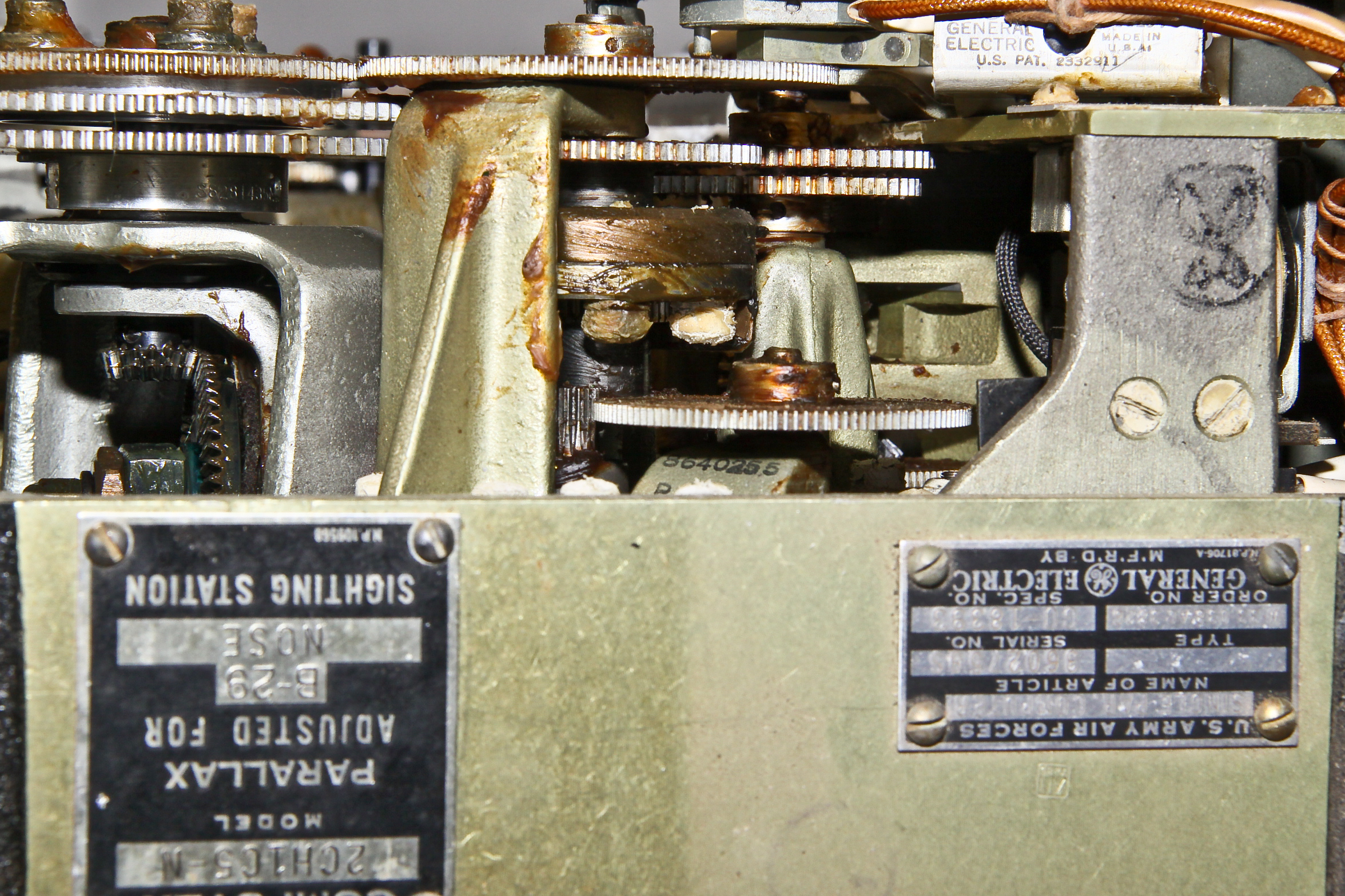

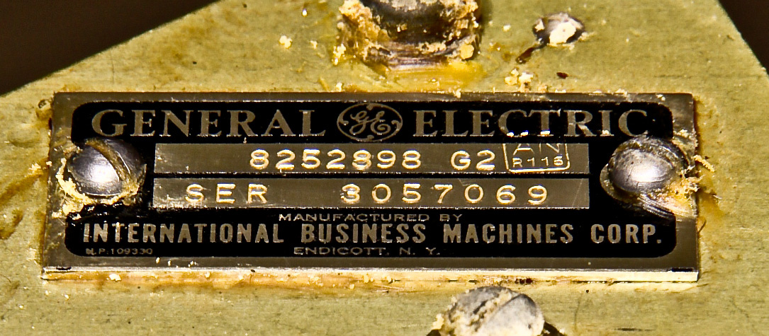
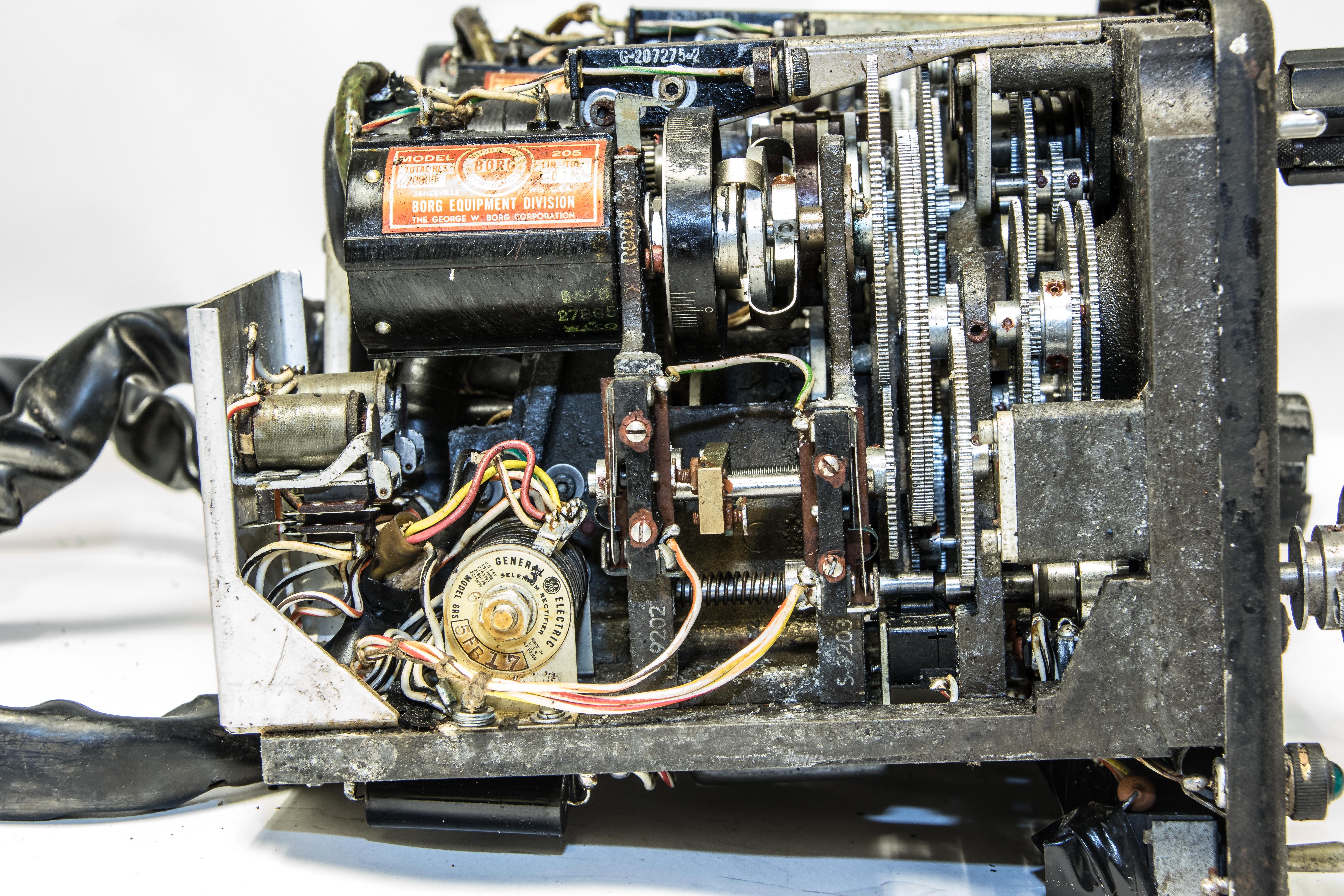
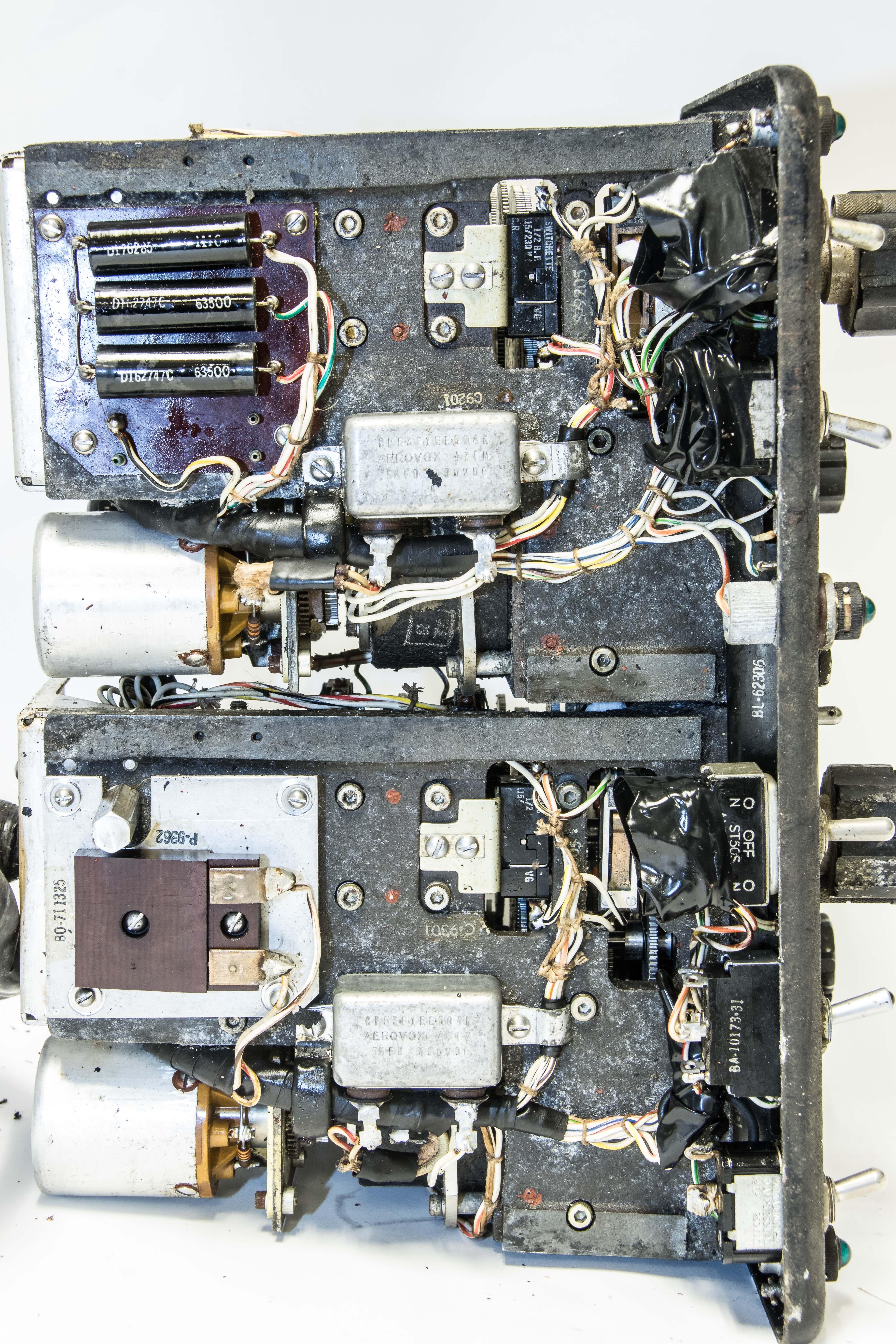
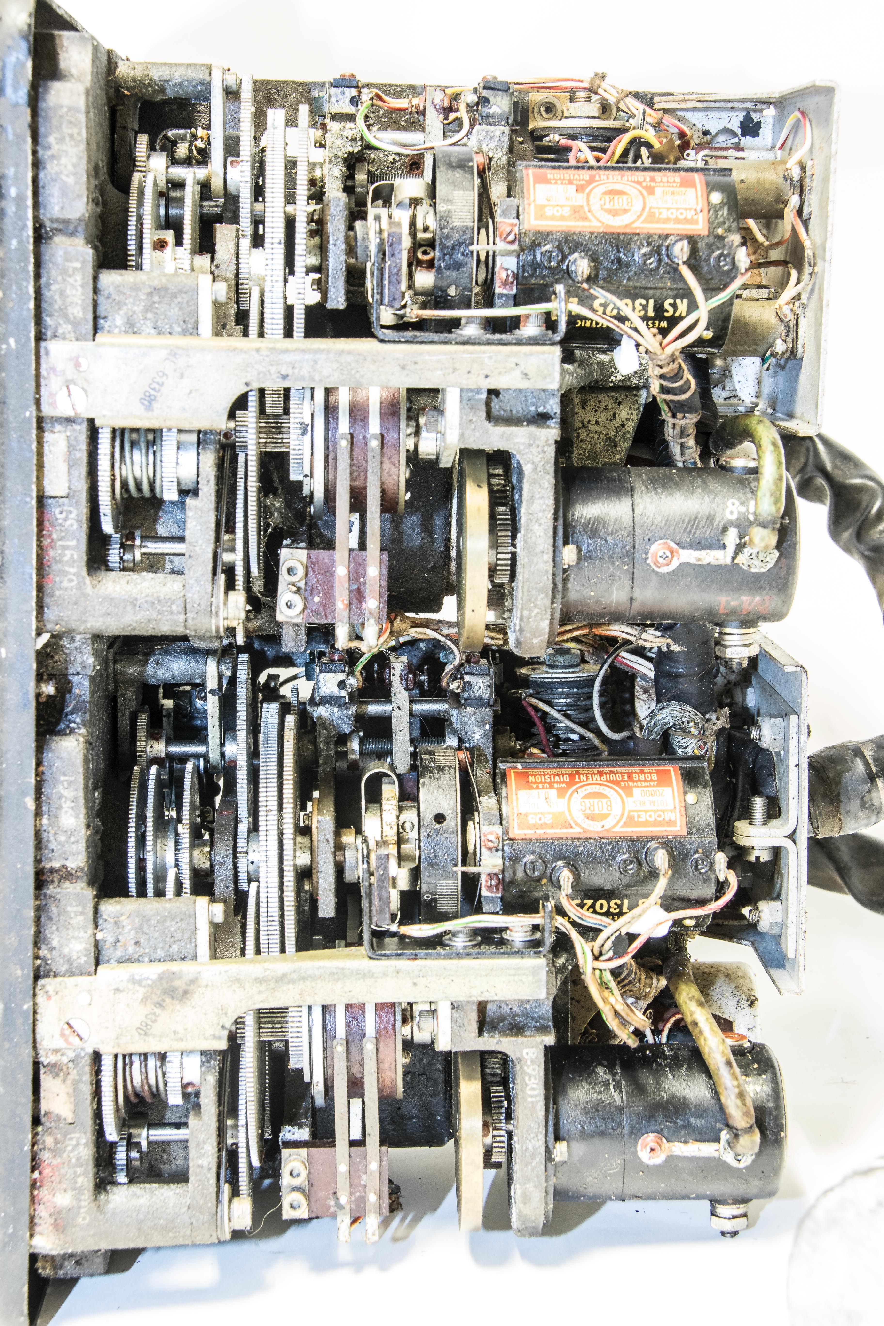
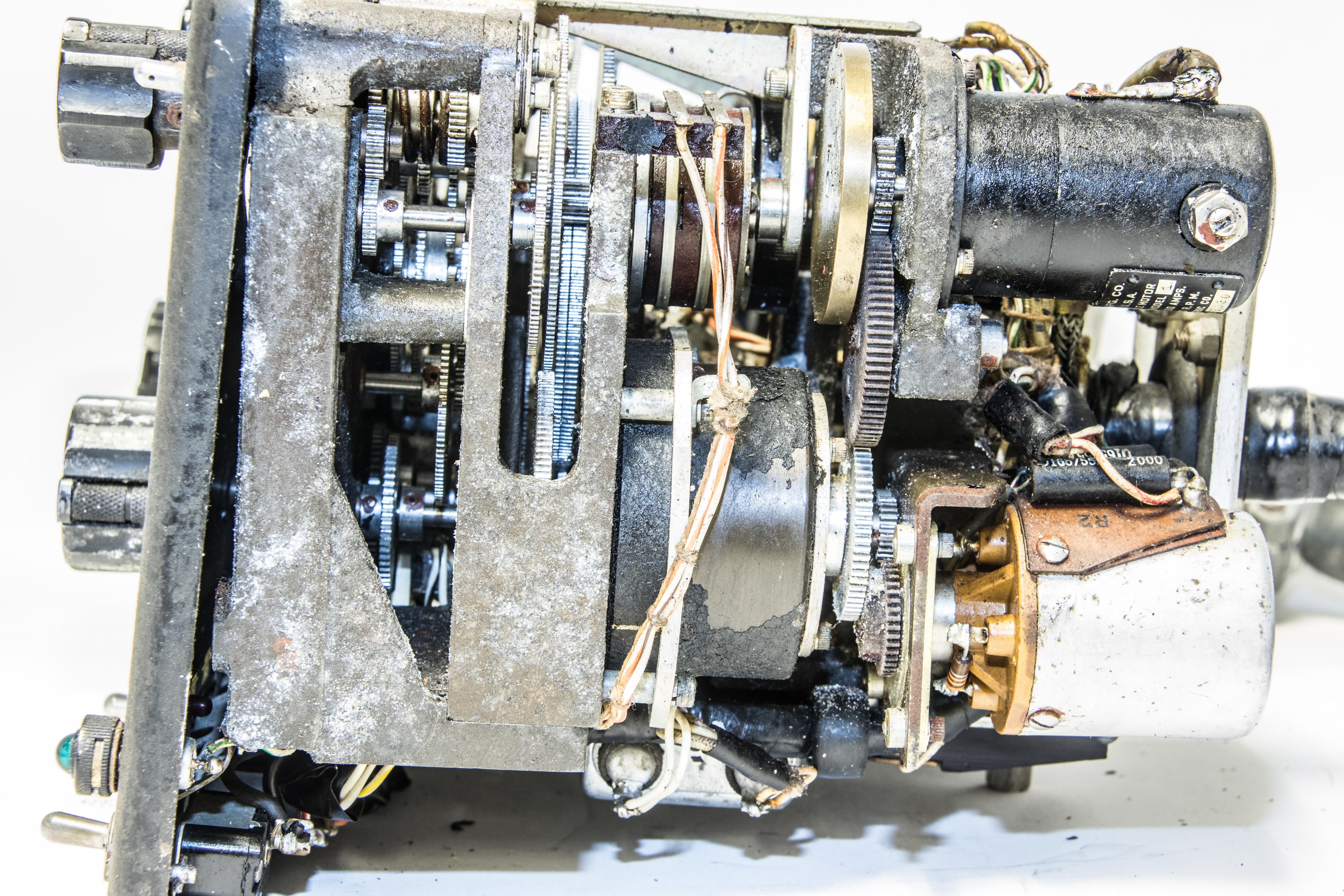
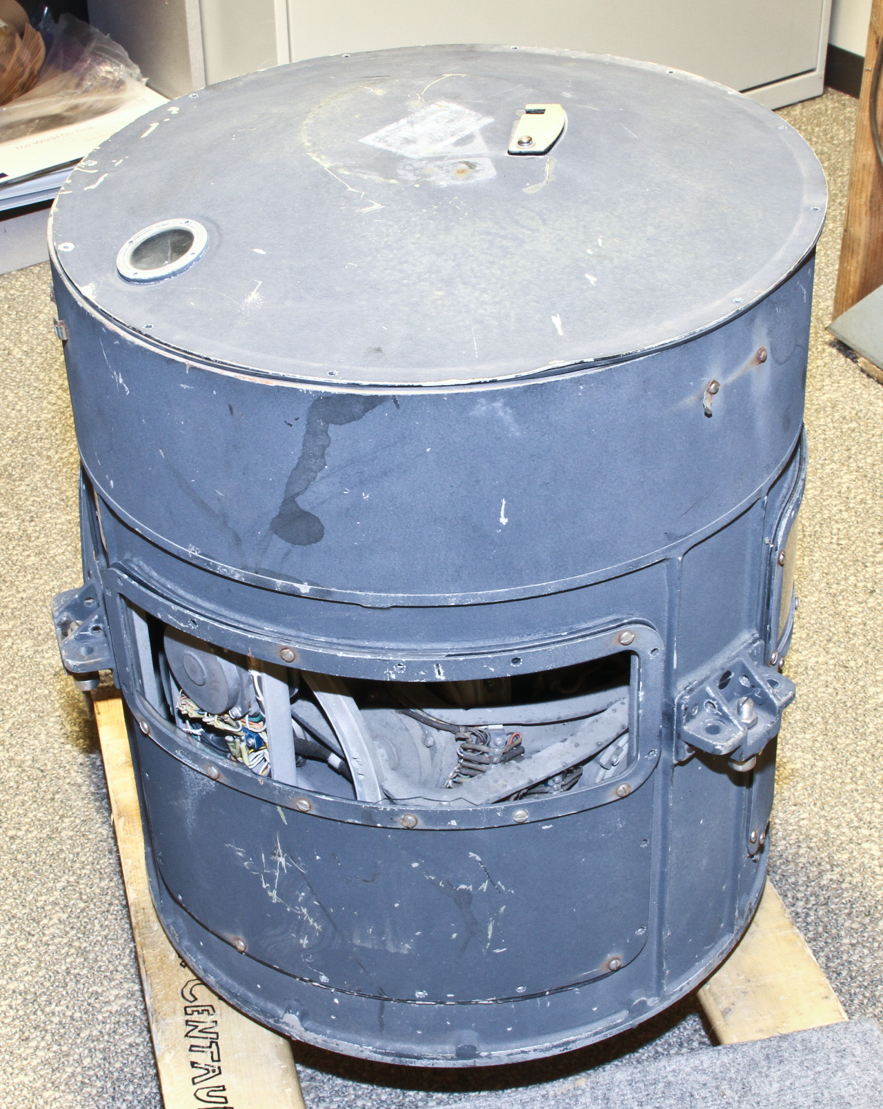
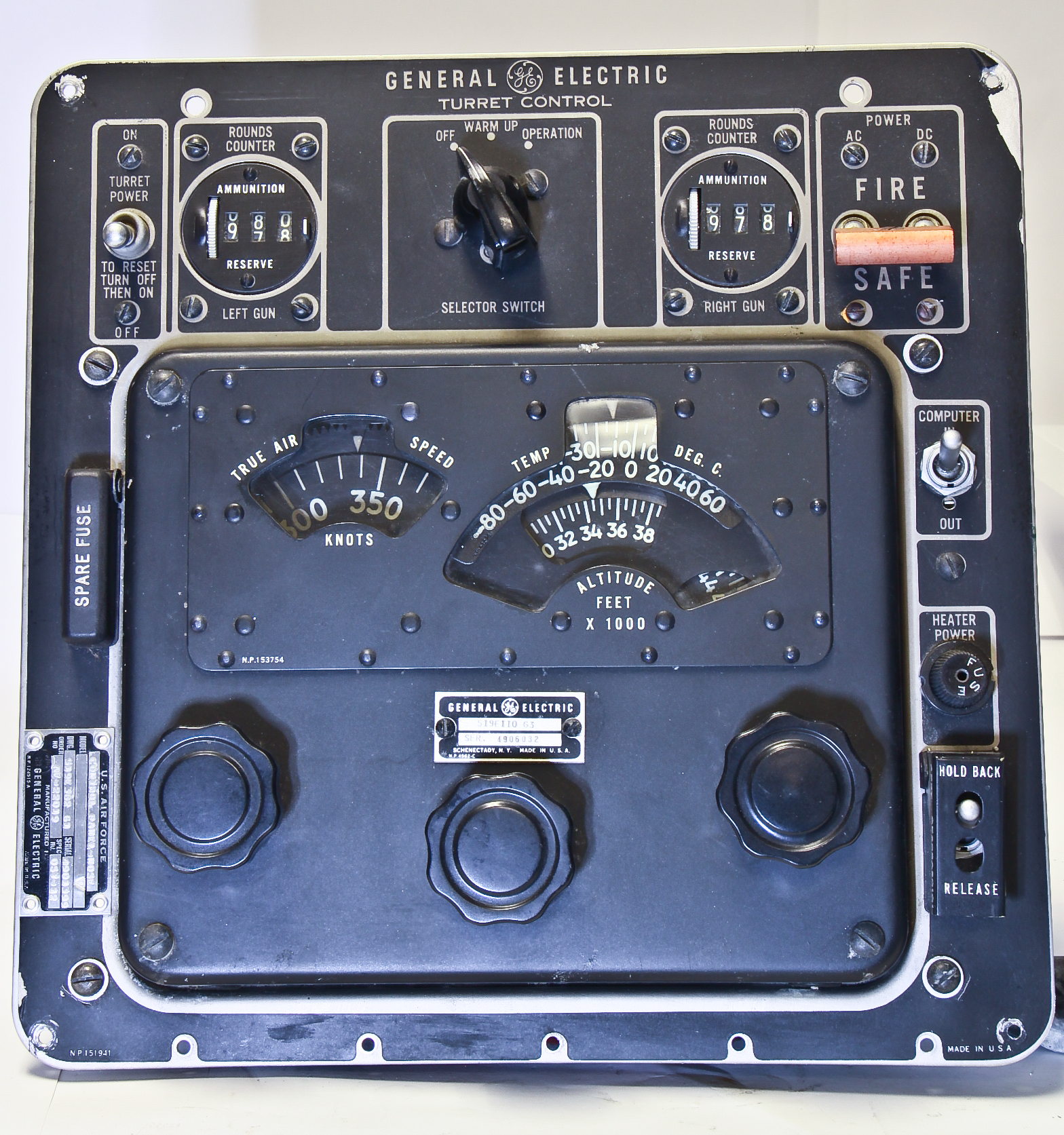
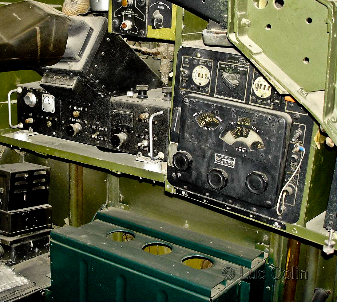
The famous B-29 bomber was a critical factor in ending World War II. It incorporated many technical innovations including a Central Station Fire Control System (CSFC) for its five gun turrets. Prior to the B-29, gun turrets in bomber such as the B-17 and B-24 contained a gunner responsible for aiming and firing the guns in the particular turret. The B-29, however, had four unmanned turrets (the tail gun was still manned) that could be (as shown in the left diagram) controlled from several remote locations: a central sighting station near the tail, a nose gunner station and the tail gunner. The advantages of the CSFC were several: smaller gun turrets (less drag), improved sighting accuracy, easier maintenance, redundancy if a sighting station is incapacitated, improved comfort for the gunners, and so forth.
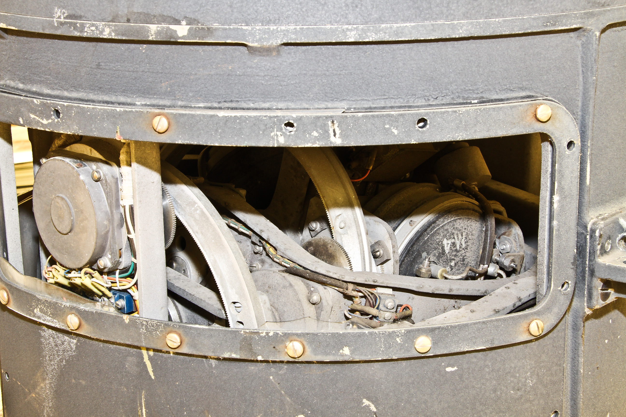
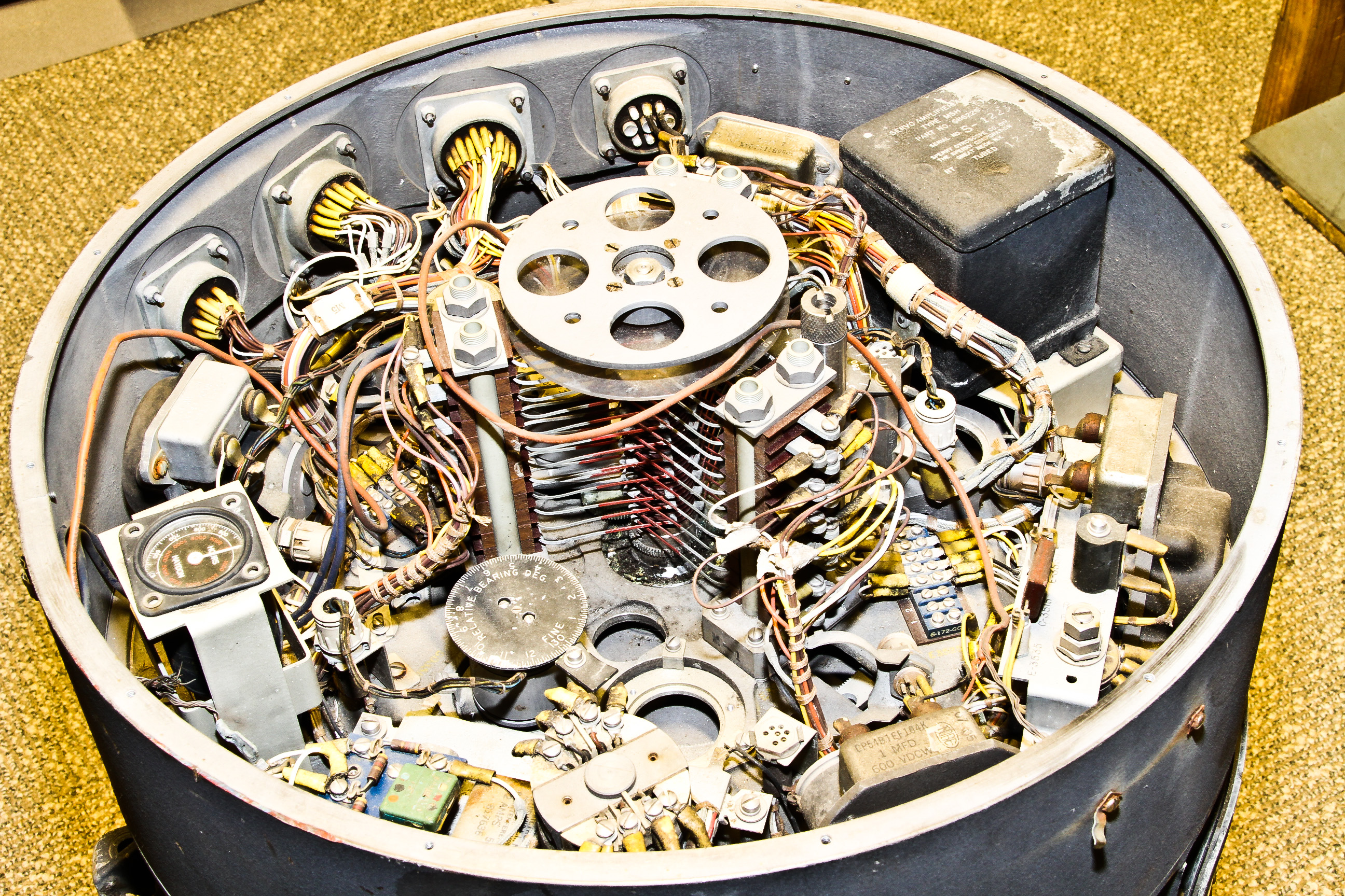
The CSFC comprised many components (e.g., servo amplifiers, motor generators, sighting heads, the gun turrets themselves), but the critical component was the computer itself, which we have. There was one computer for each of the five sighting stations. Based on information from the sighting station along with the plane's altitude, air-speed, and temperature, the computer calculated the proper aiming of the turret considering ballistic factors (wind and gravity), parallax (offset between gun and sighting head) and the appropriate lead to the target based on range and relative velocity of the target.
Shown here are:
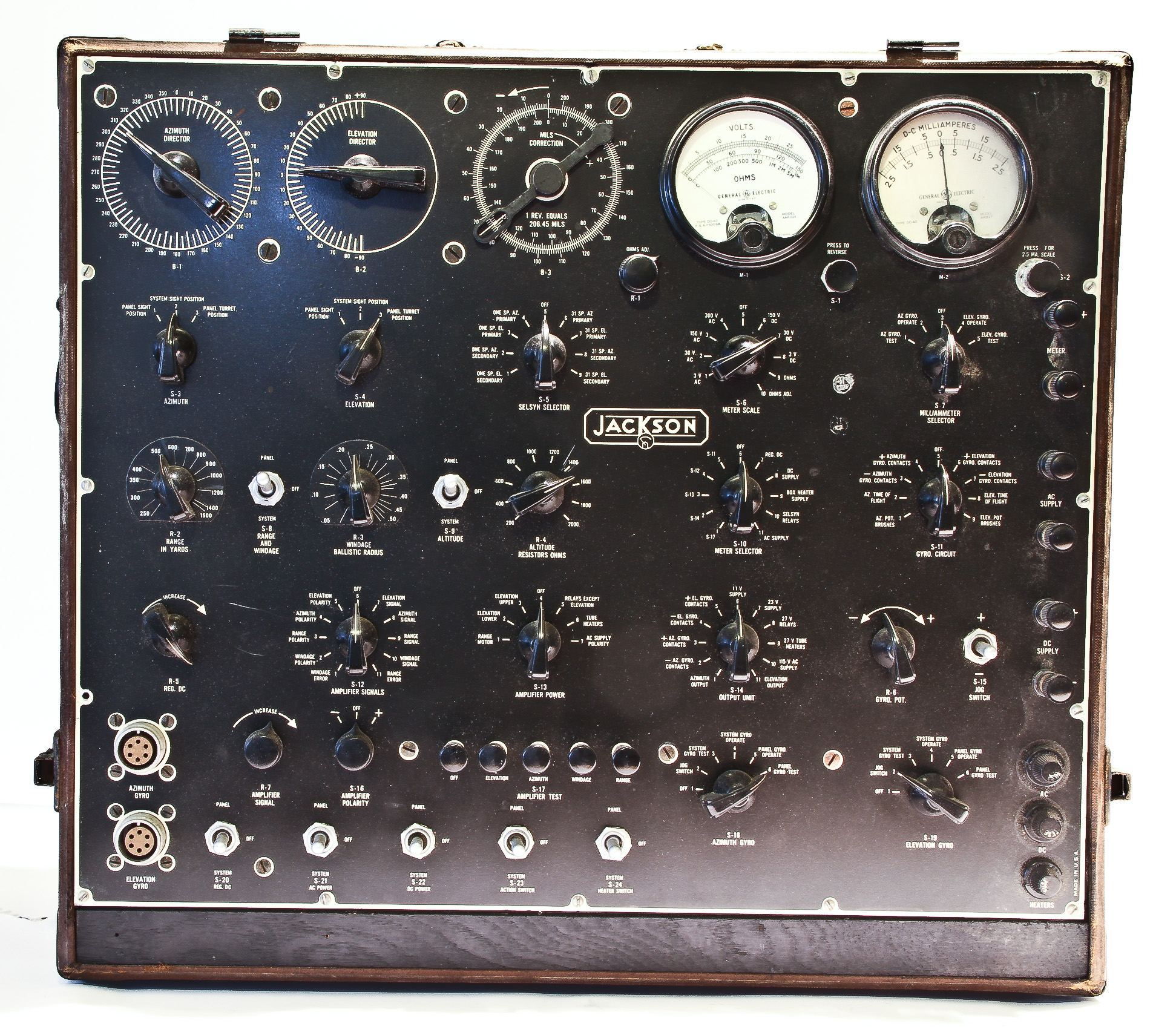
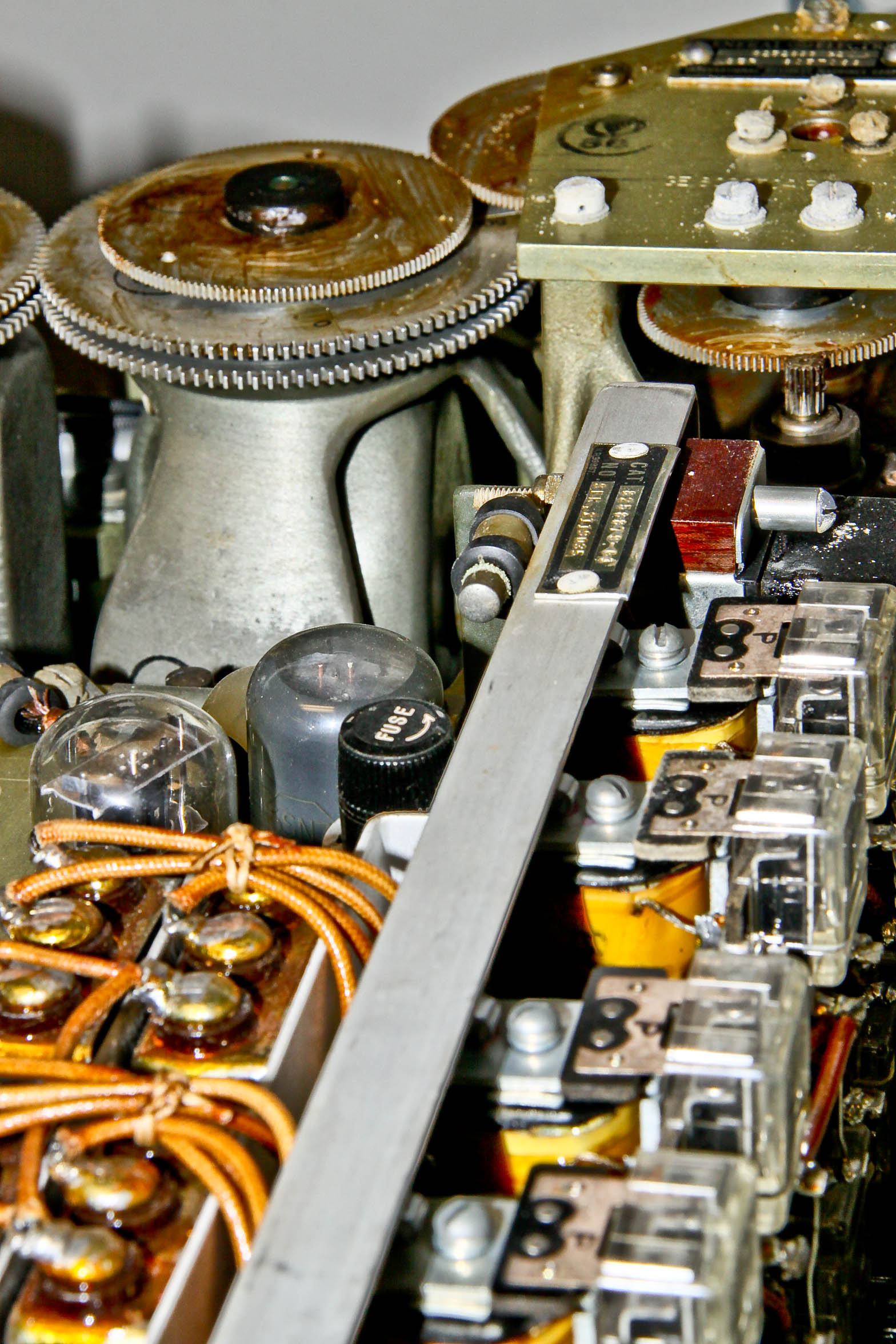
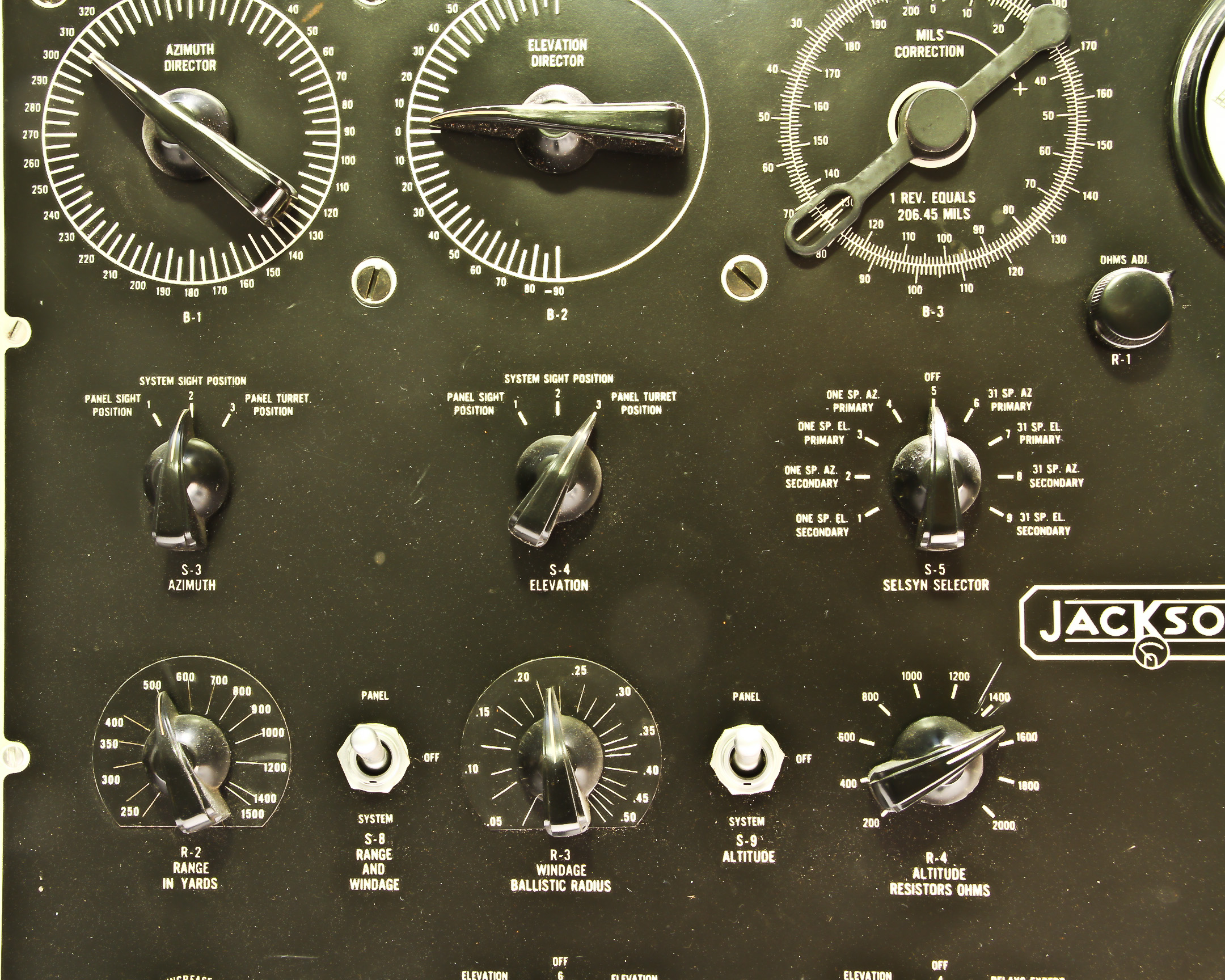
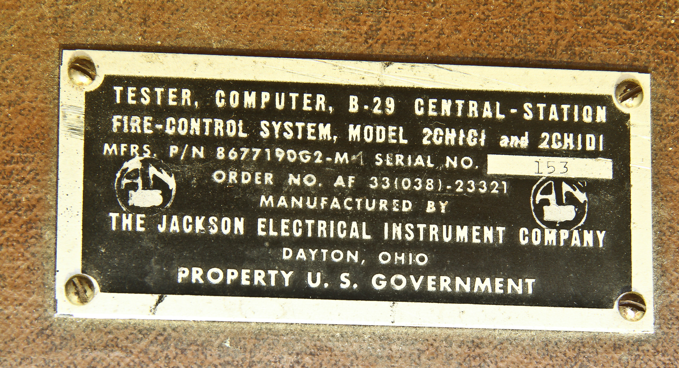
We also have the tester for this computer. Figures 9, 10, and 11 show the tester.

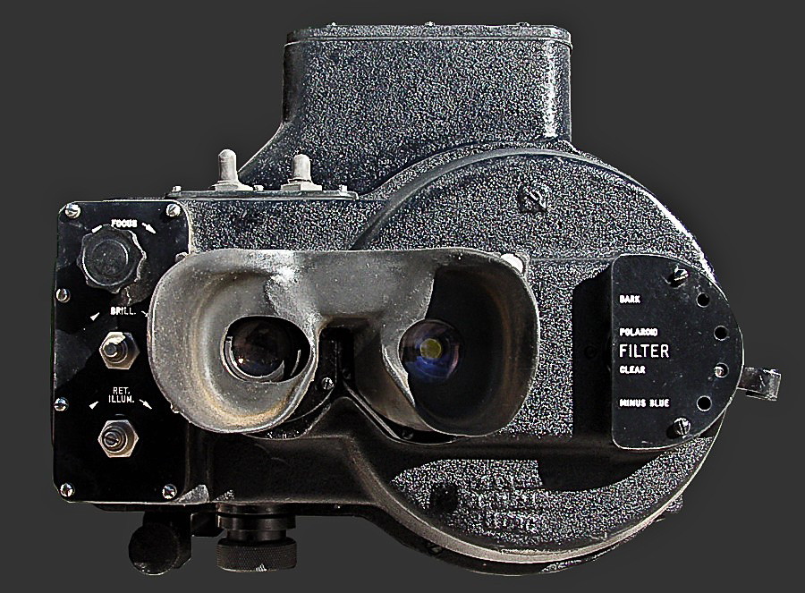
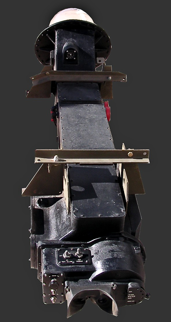

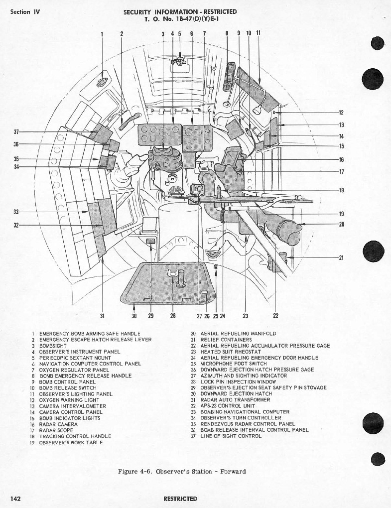
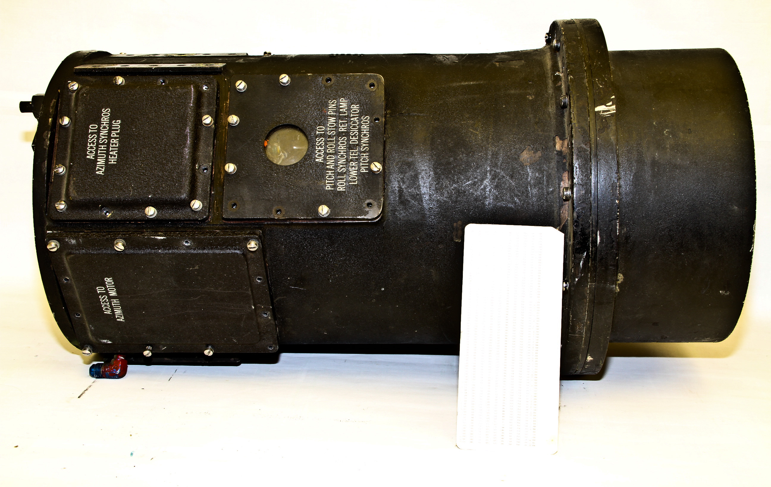
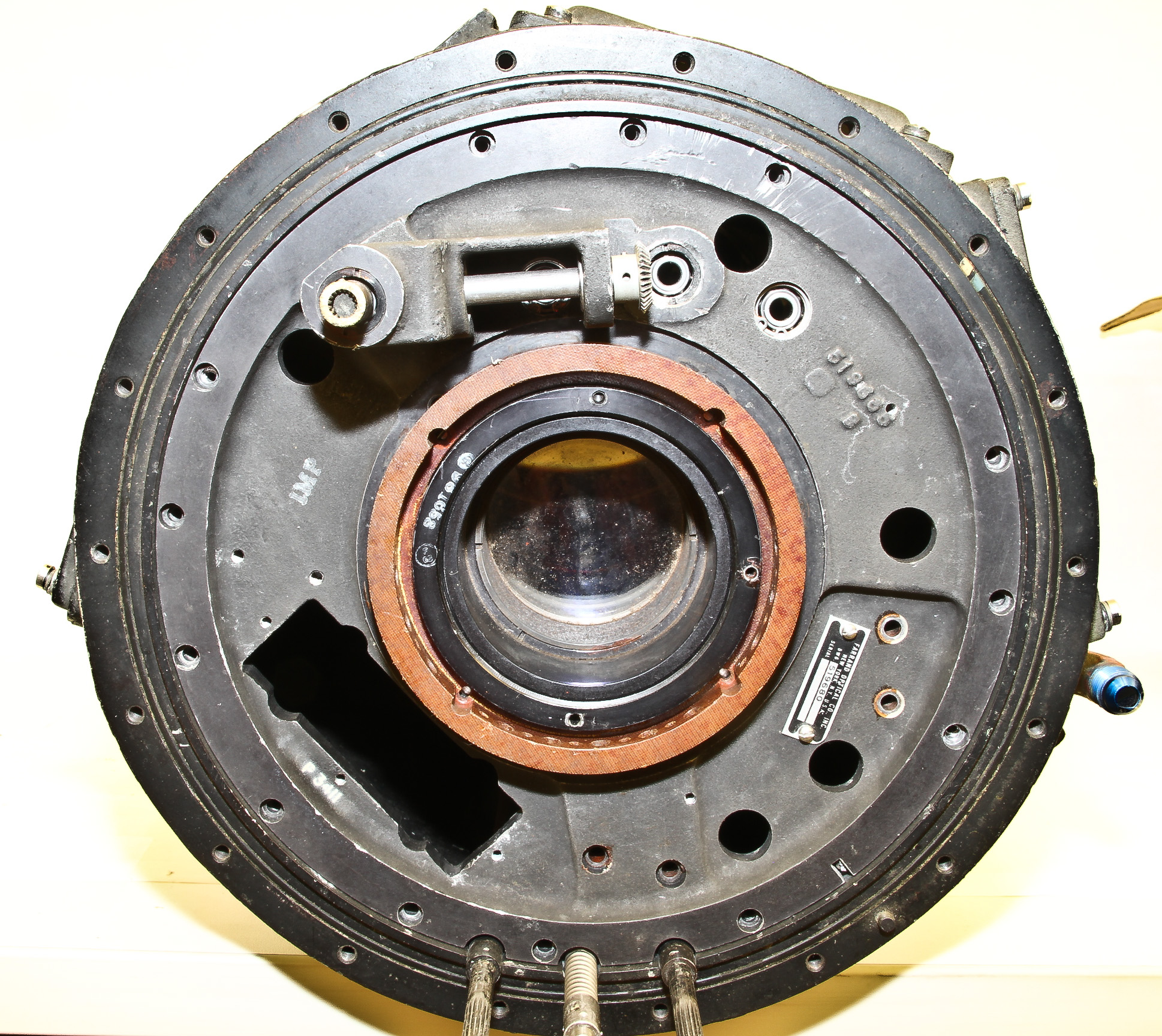
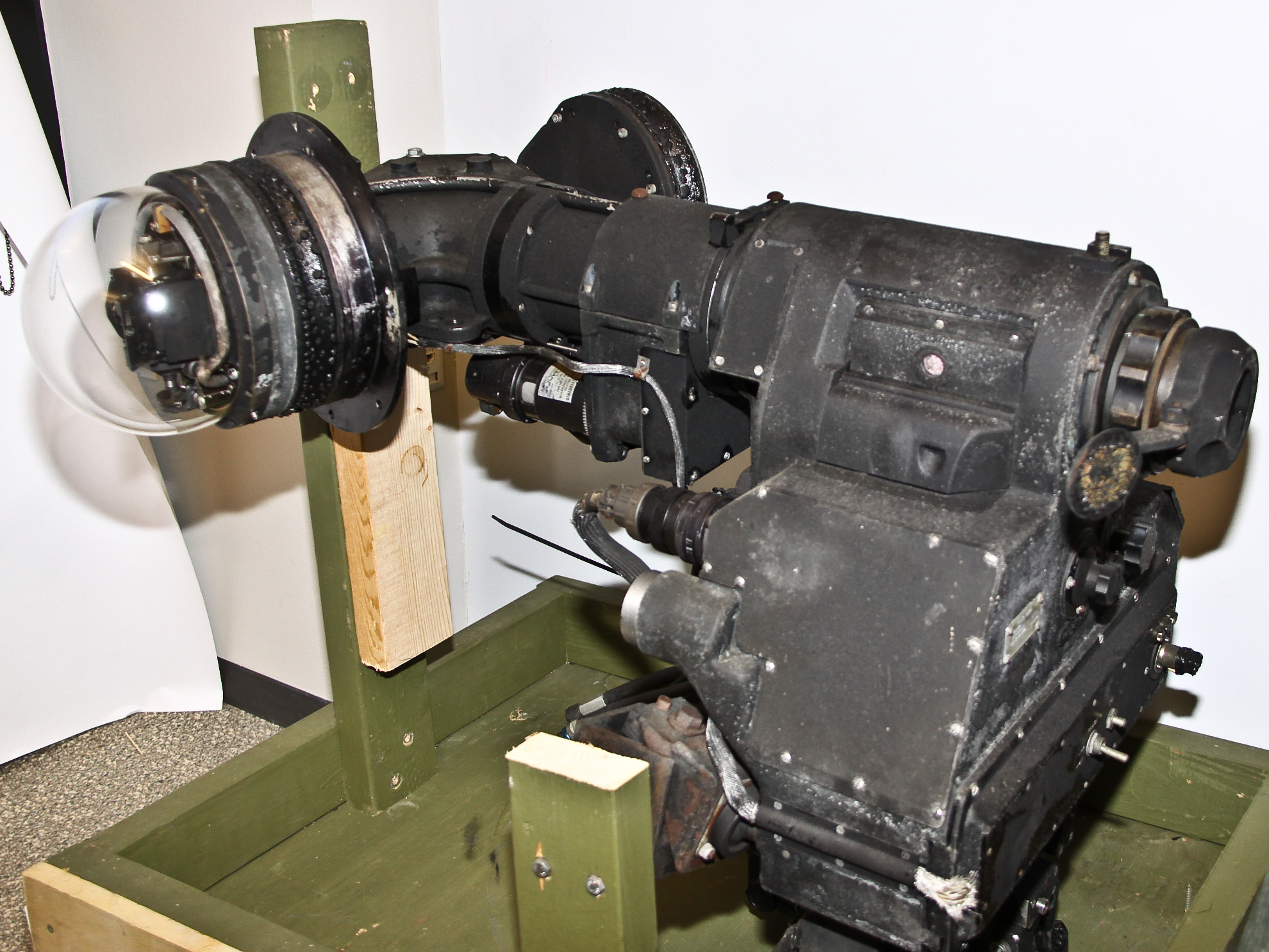
Here is a Y-4 optical bombsight used in the Boeing B-47 bomber (specifically the B-47B and B-47E models). It is huge; on the left is the bombsight being wheeled into my office. It's about 6 feet long and weighs about 200 lbs. (Figure 1 is actually upside down; Figure 2 is a picture of it right side up).
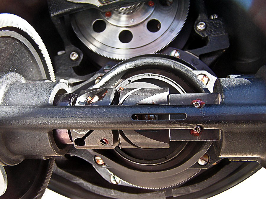
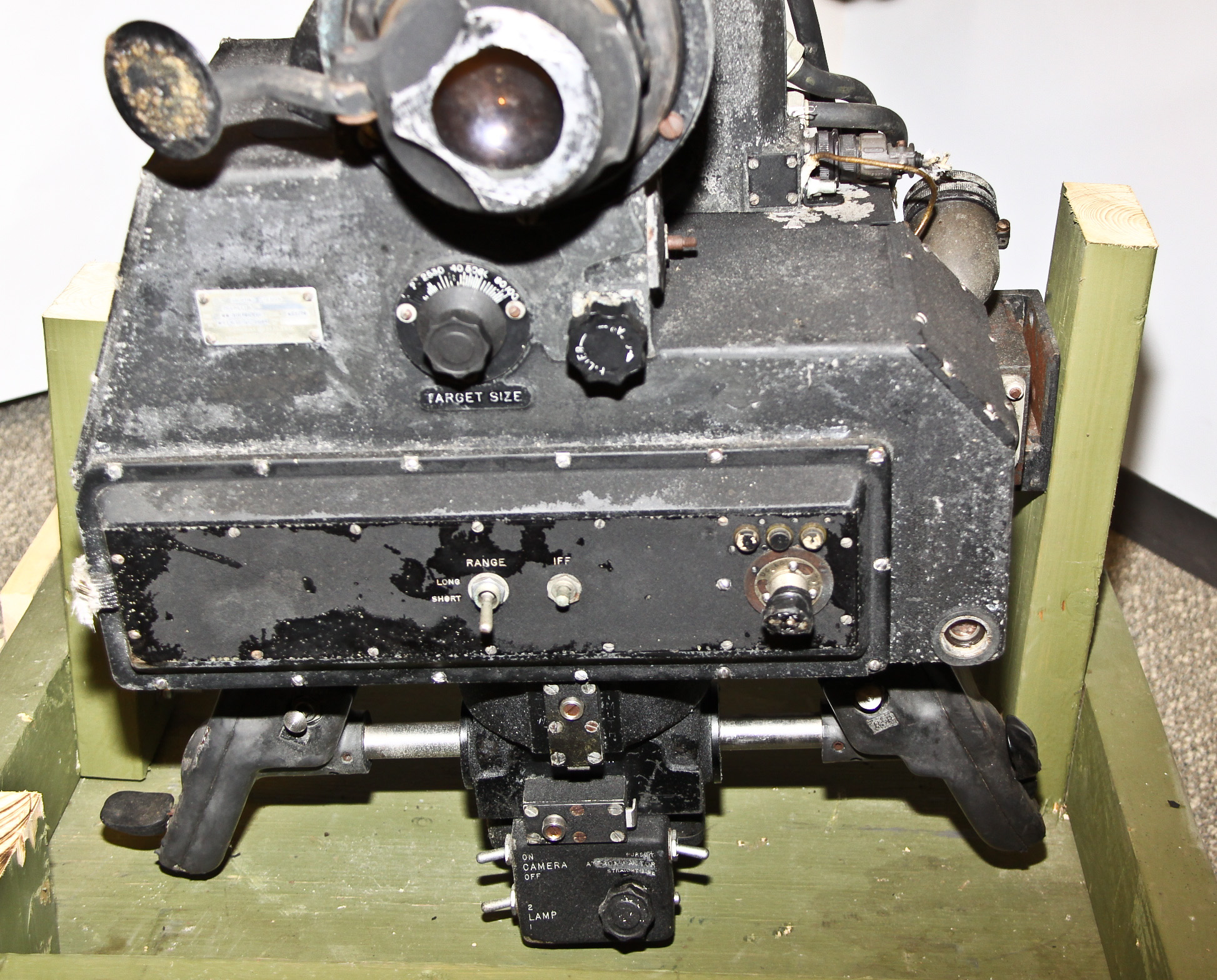
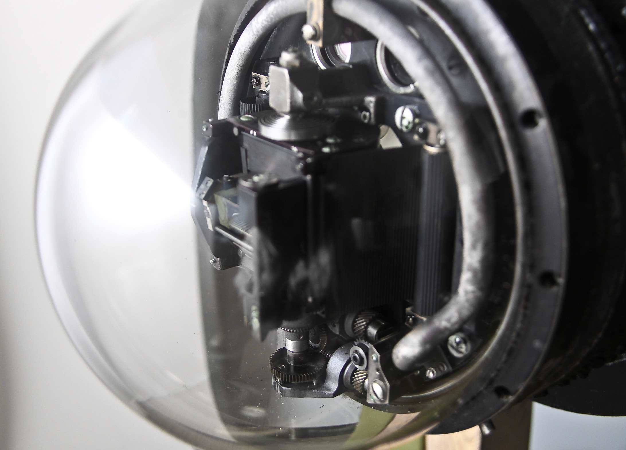
Figure 3 is a drawing from the Air Force Museum site showing the location of the Y-4 in the bombardier-navigator compartment in the nose of the B-47. The Y-4 bombsight provided an optical view of bombing targets through the glass bubble which protuded from the nose of the aircraft. The geared lens mount inside the bubble (a closeup is shown on the right) moved as the plane moved to keep the line-of-sight on the objective. Unlike the World War II bombers of the previous decade, this allowed the pilot to take evasive action as he approached the target without the operator losing his aiming point.
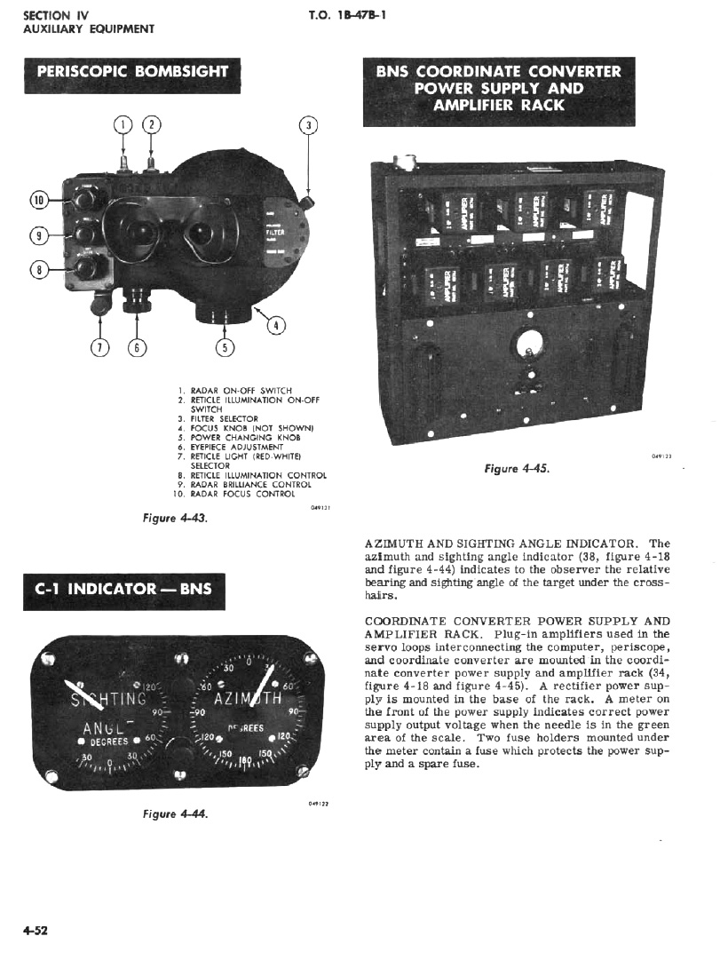
Figure 5 shows the bombardier's viewing port. The left eyepiece show the optical view from the external sight. The right eyepiece show a copy of the azimuth view of the bombing radar.

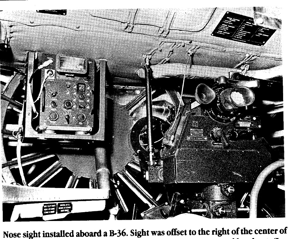
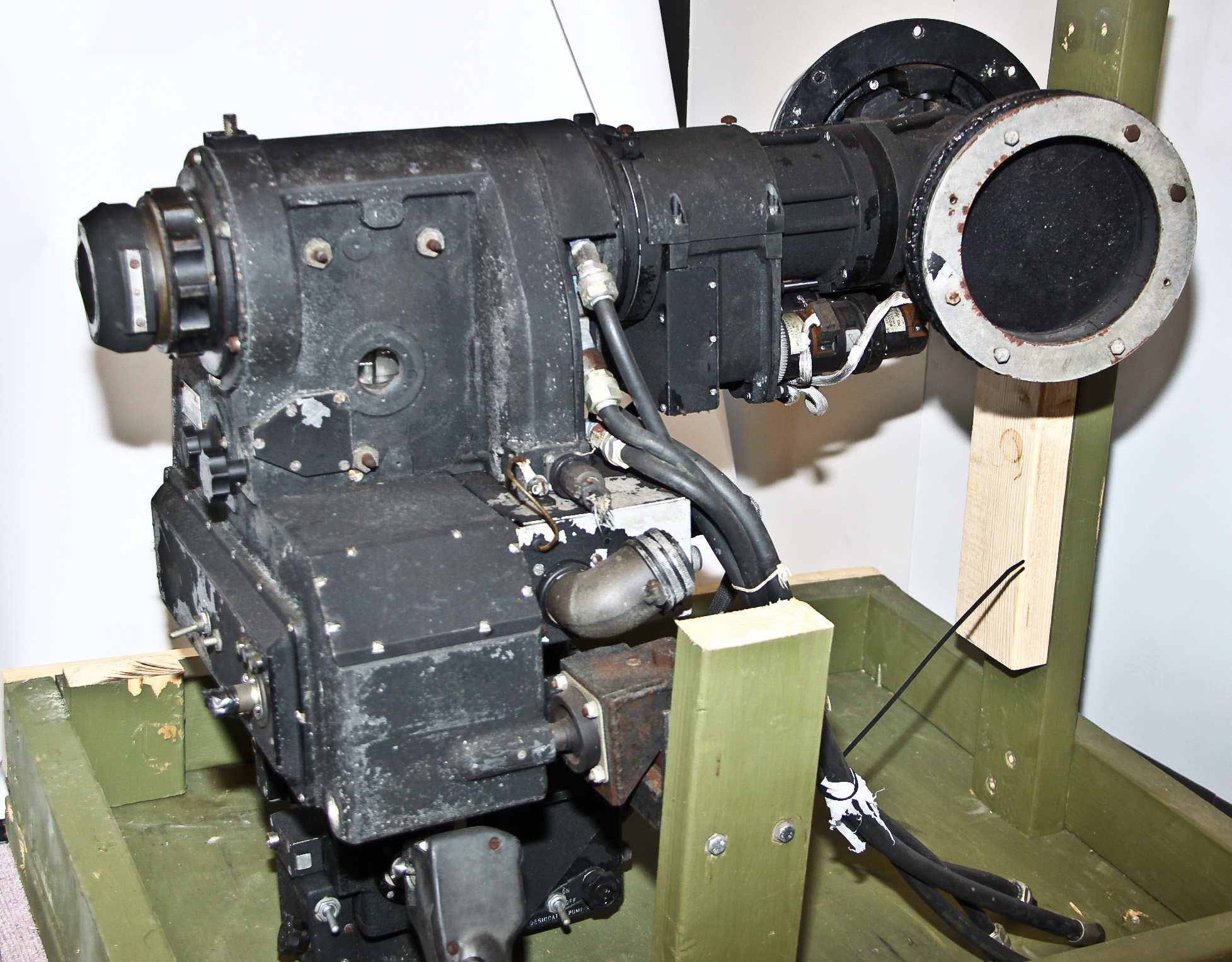

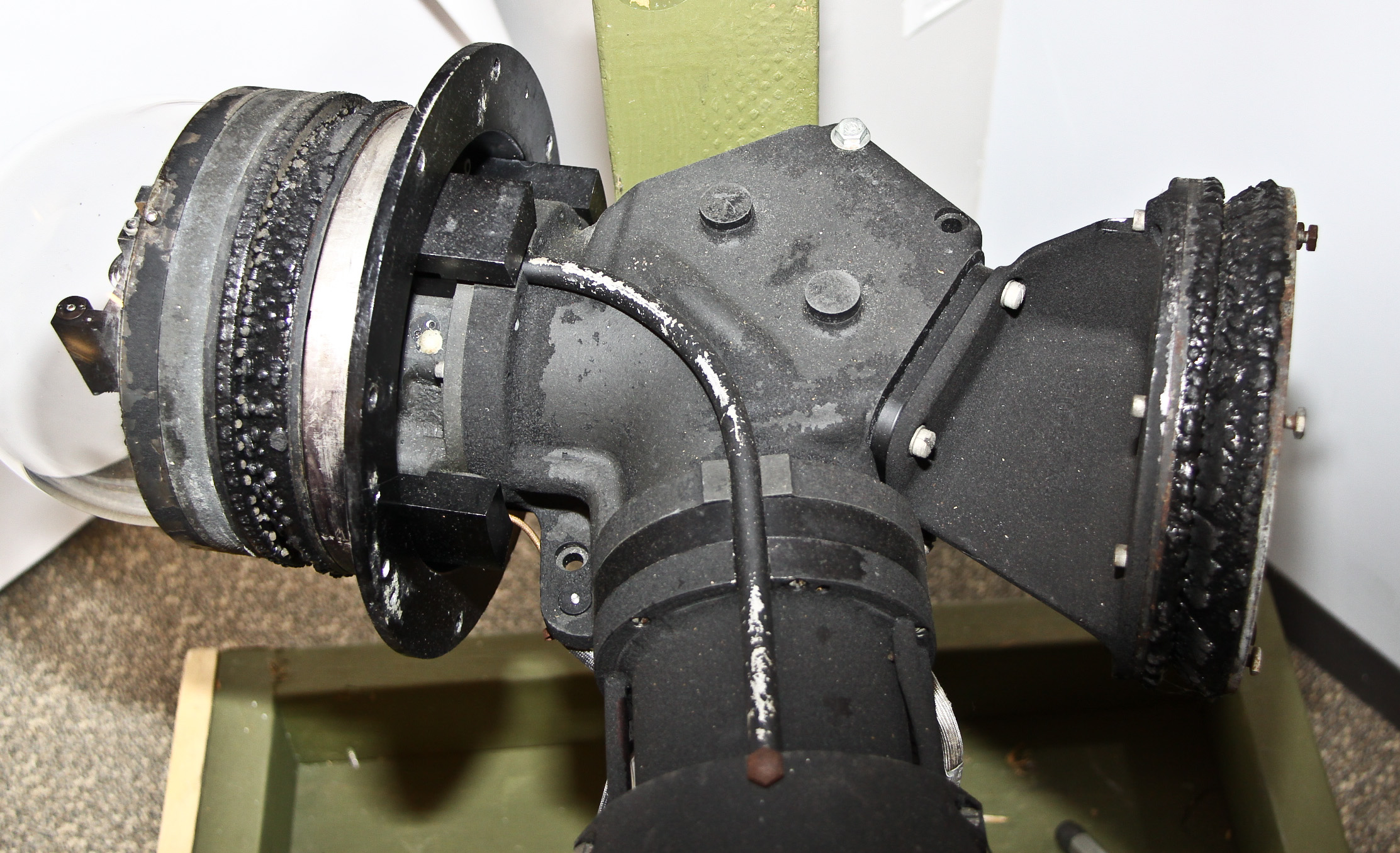
NOTE: the following identification of the item as a B-36 Bombsight is now known to be wrong, but I'm leaving the old description in for continuity purposes. Also, the device description stuff in this old section is still applicable.
Here is the nose sight for the bombsight used in the giant Convair B-36 bomber. It is heavy (about 150 pounds); on the left is the sight in my office. On the right is a picture of a sight mounted in the nose of a B-36.
The nose sighting station is a horizontally-mounted, double-prism periscopic sight that gave the gunner a complete hemisphere of vision when sighting through the eyepiece. The sight has at its forward end a spherical glass dome head which projected through the nose of the B-36. Rotation of the gunner's hand grips positioned scanning prisms located in the head.
This sight was manufactured by Farrand Corporation; General Electric was the integrator of the B-36 gunnery system. Apparently, the ability to view an entire hemisphere without moving the observer's head was an non-trivial invention and Farrand patented it (under the strange name of "Scanning Telescope Having Asigmatized Pupil", U.S. Patent 2719457). Here's a quote from this patent: "The system illustrated is useful as a gun sight for the control of remotely operated guns which customarily use the polar coordinate system. This is particularly true of aircraft installations." (Shortly after this patent issued, Farrand sued the government for "unauthorized use" [D.C.S.D.N.Y., 175 F.Supp. 230; D.C., 197 F.Supp. 756]. The result was appealed to the U.S. Circuit Court of Appeals and is an interesting case relative to the patent concept of "reduction to practice". But I digress...).
Even though it seems obvious that this is a B-36 nose sighting station, there are some mysteries. Instead of looking directly ahead, the optical path is slanted as if the observer looks at a 60 degree angle to the nose. The pictures seem to imply a more straightforward alignment. Also, what about the other arm of the Y-shaped nose? I believe it is a port for a camera attachment, but I don't really know.
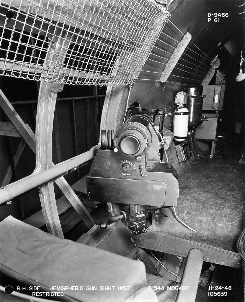
Apparently this is a gunsight specifically designed for a never-produced B-54 bomber. Someone who knows more than I do just sent me the following:
I was just browsing for more information on Hemispheric Gunsights and found your page. You note that the B-36 gunsight you have does not appear to be correct for the B-36 nose installation. I believe you are correct. I believe that your gunsight was actually produced for the cancelled B-54A, the final "evolution" of the B-29. Pictures were recently posted in a thread on the WIX forum that shows the exclusive use of hemispheric gunsights and the waist intallations look quite similar to yours.
While the B-54A was never built, they did start construction of the prototype, and as the gunsights tend to be "long lead" items, it's feasible that yours was built in anticipation of installation on a testbed aircraft (probably a B-50) to test the system prior to flying on the B-54.
I highly recommend the above link (as well as the WIX site in general). Now all is explained about the wierd angled viewport. If you look at "pg60" and "pg61" of the pictures in the link, you can see a mockup of how the sight looked out of the fuselage at an angle. Figure 9 is a copy of one of these pictures.

World War II gave rise to some amazing electromechanical computers used by the military. The most impressive was the Navy's Mark I and Mark 1A fire control computers used on battleships. A great reference to this device and many similar electromechanical fire control devices can be found in this site.
Figures 1-3 show a "Powder Fuze Ballistic Computer". The device is labeled as being for a Mark I computer, and there is a clear picture of this component in the maintenance manual for the Mark I.
Figures 4-5 show a second component that I think comes from a Mark I, but cannot prove it.
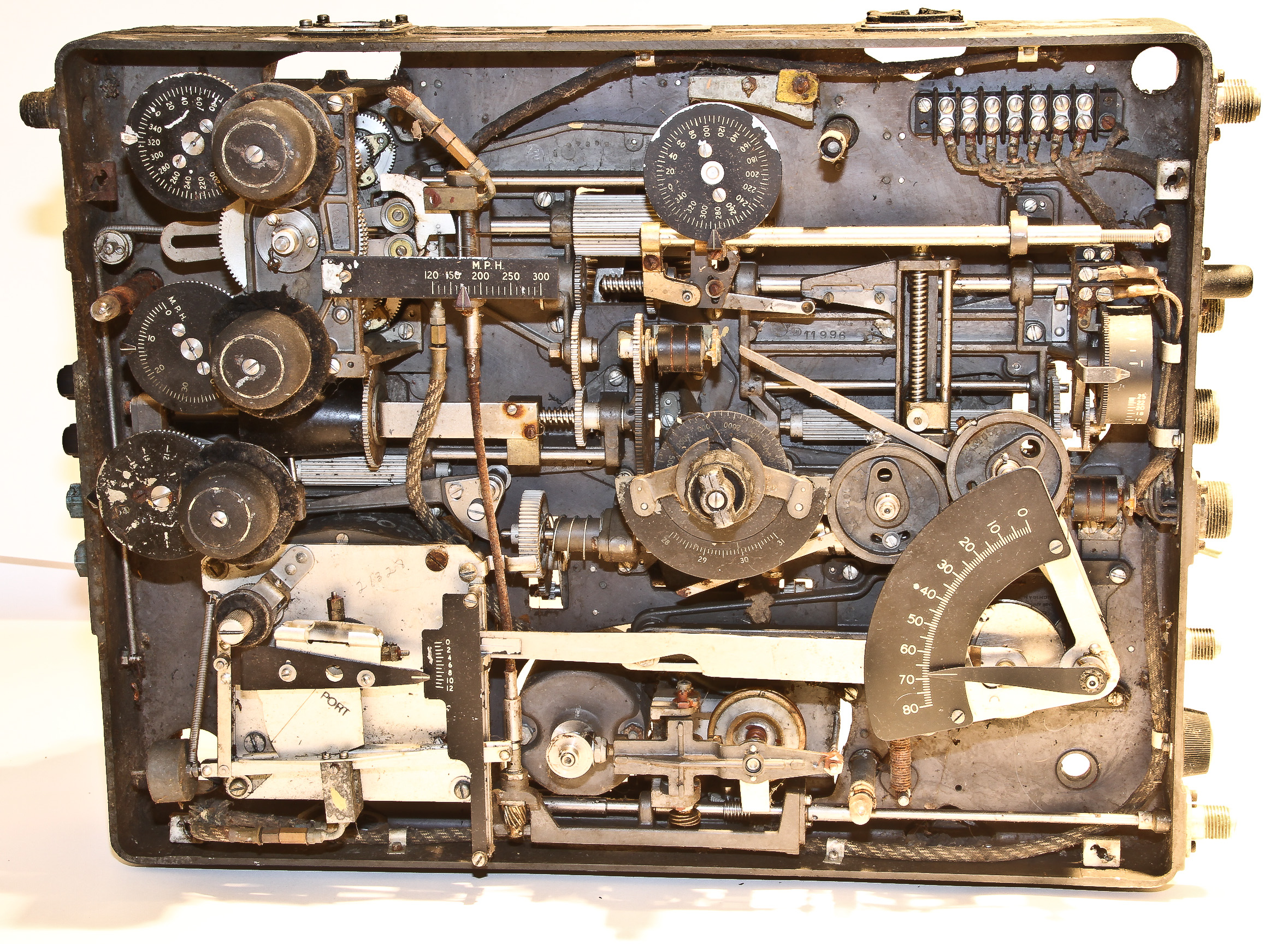
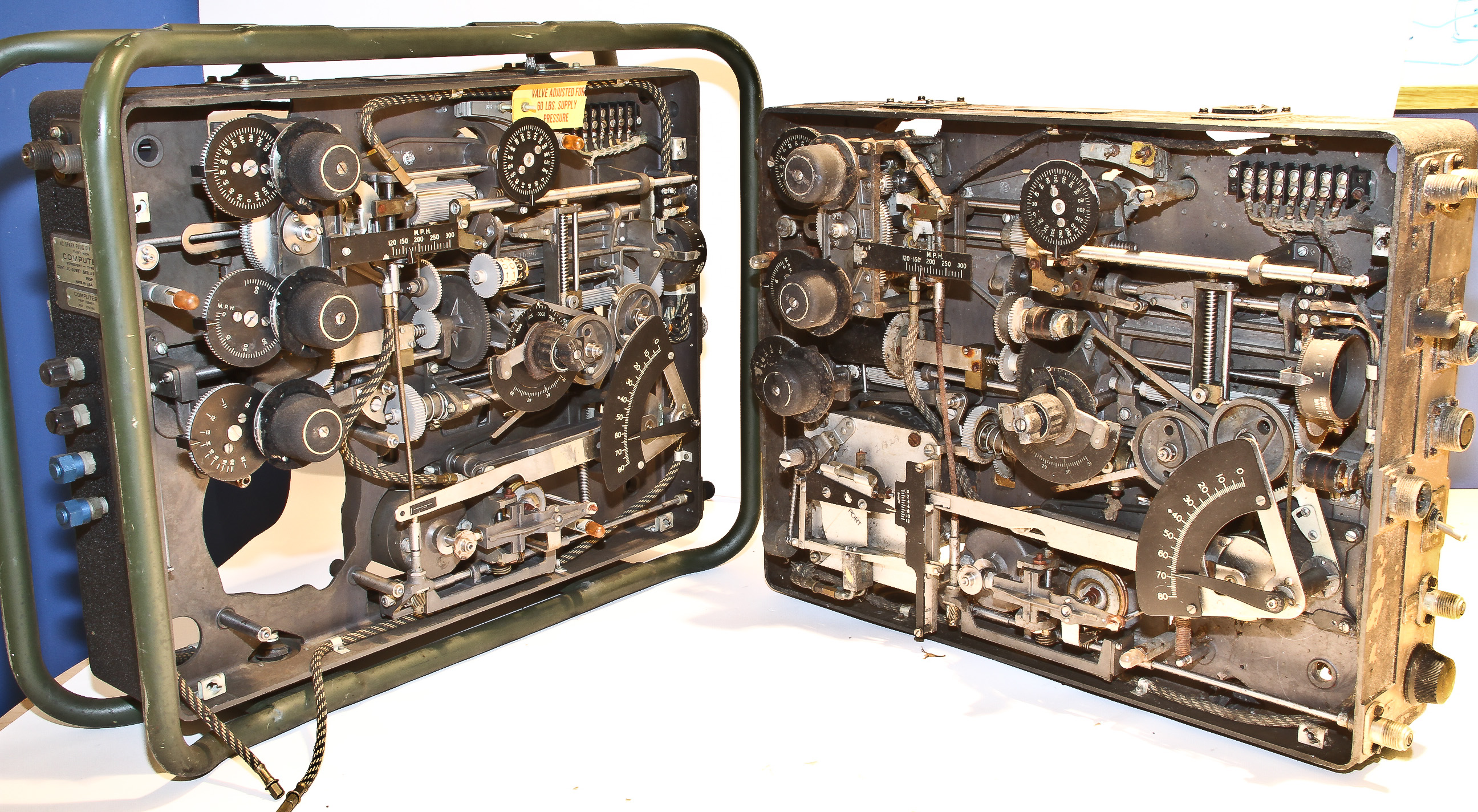
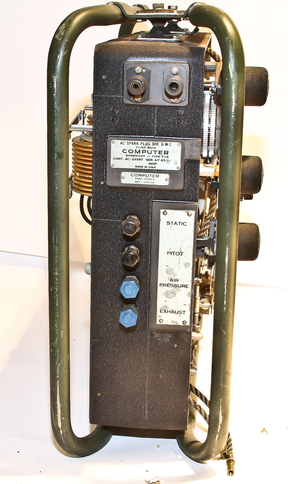
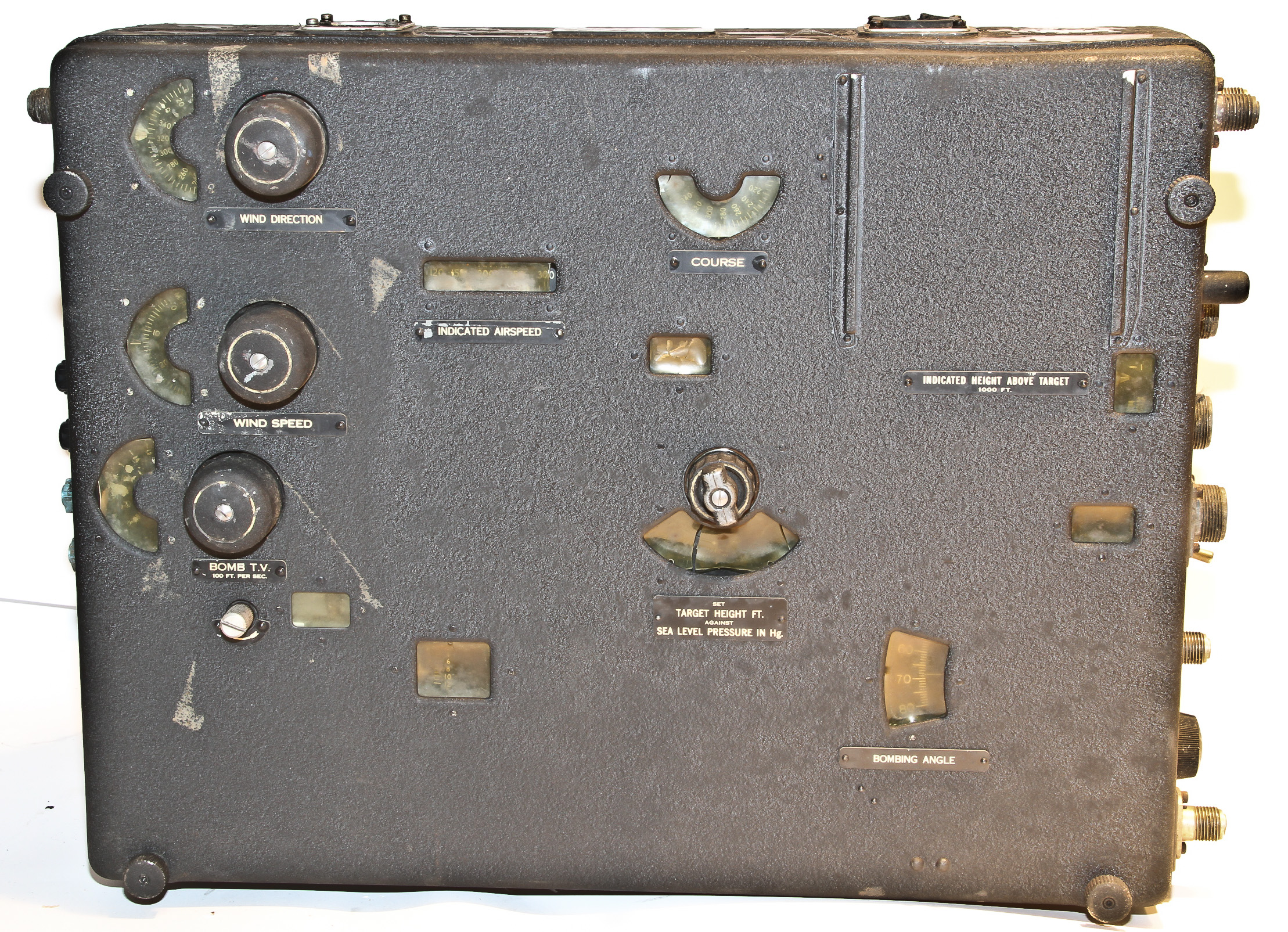
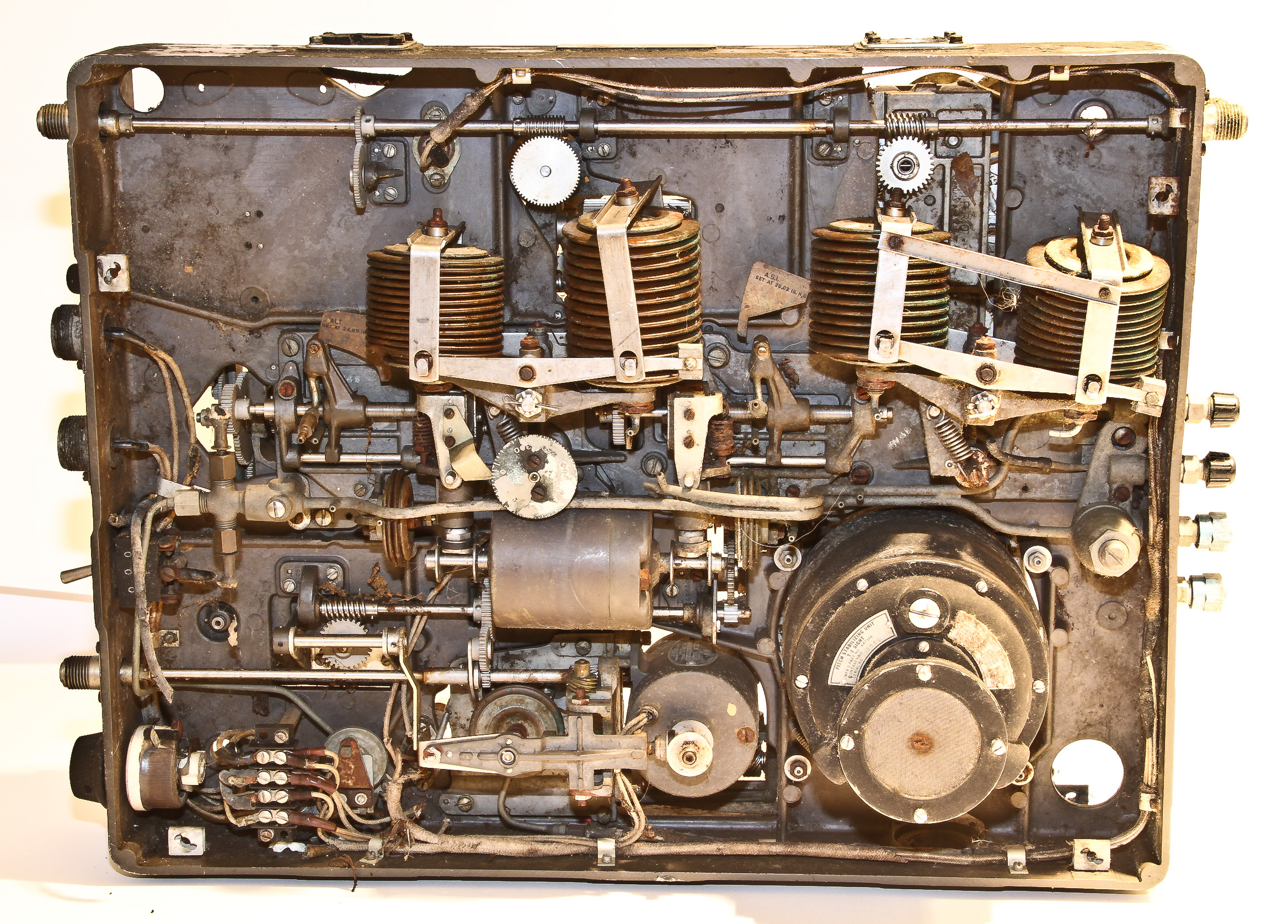
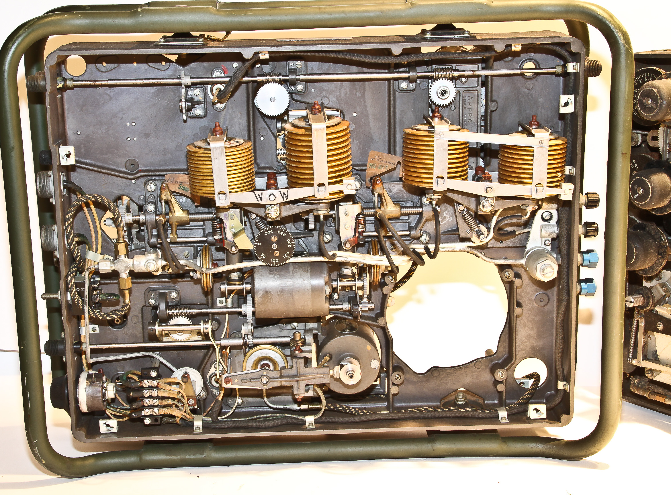
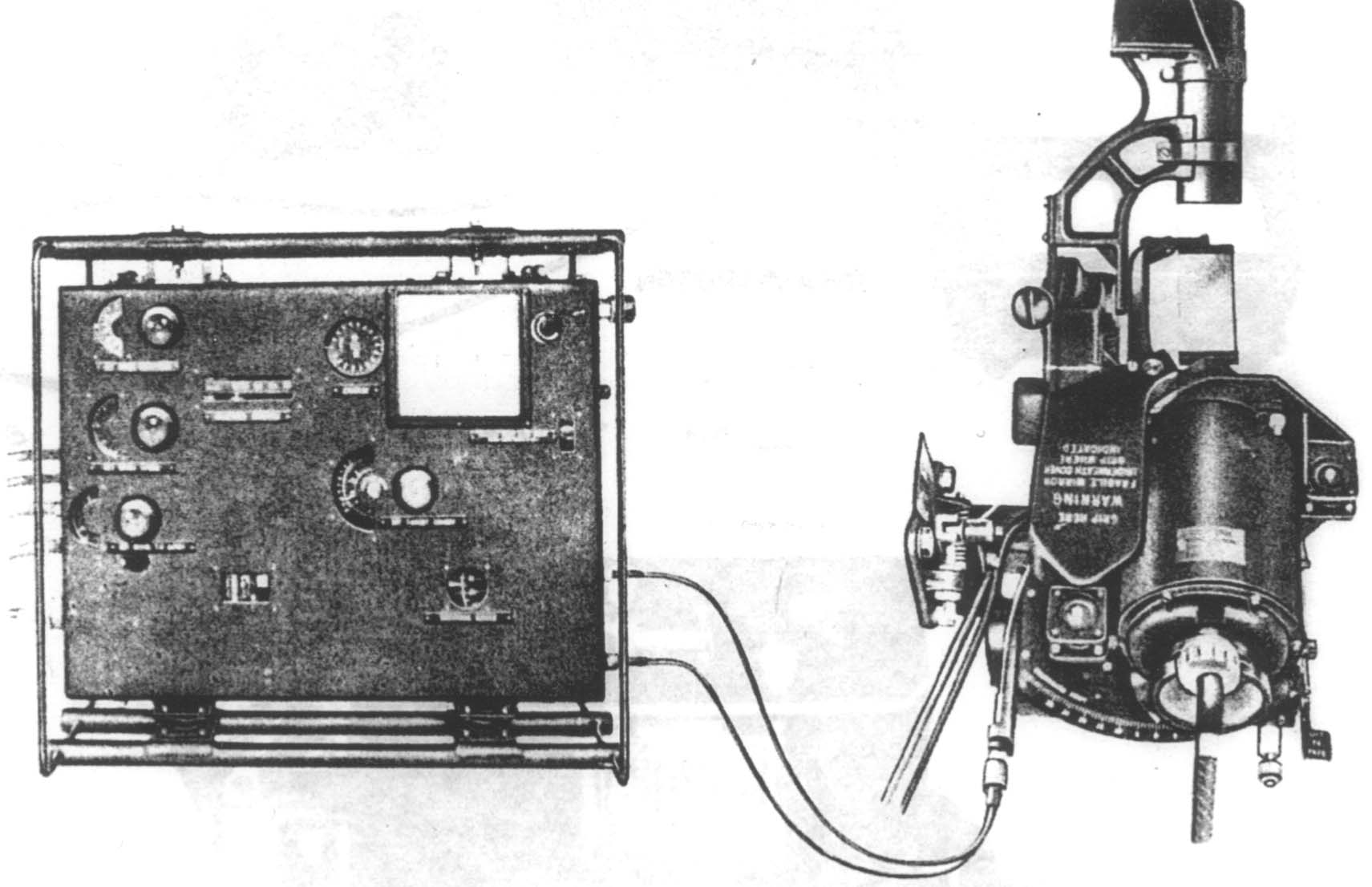
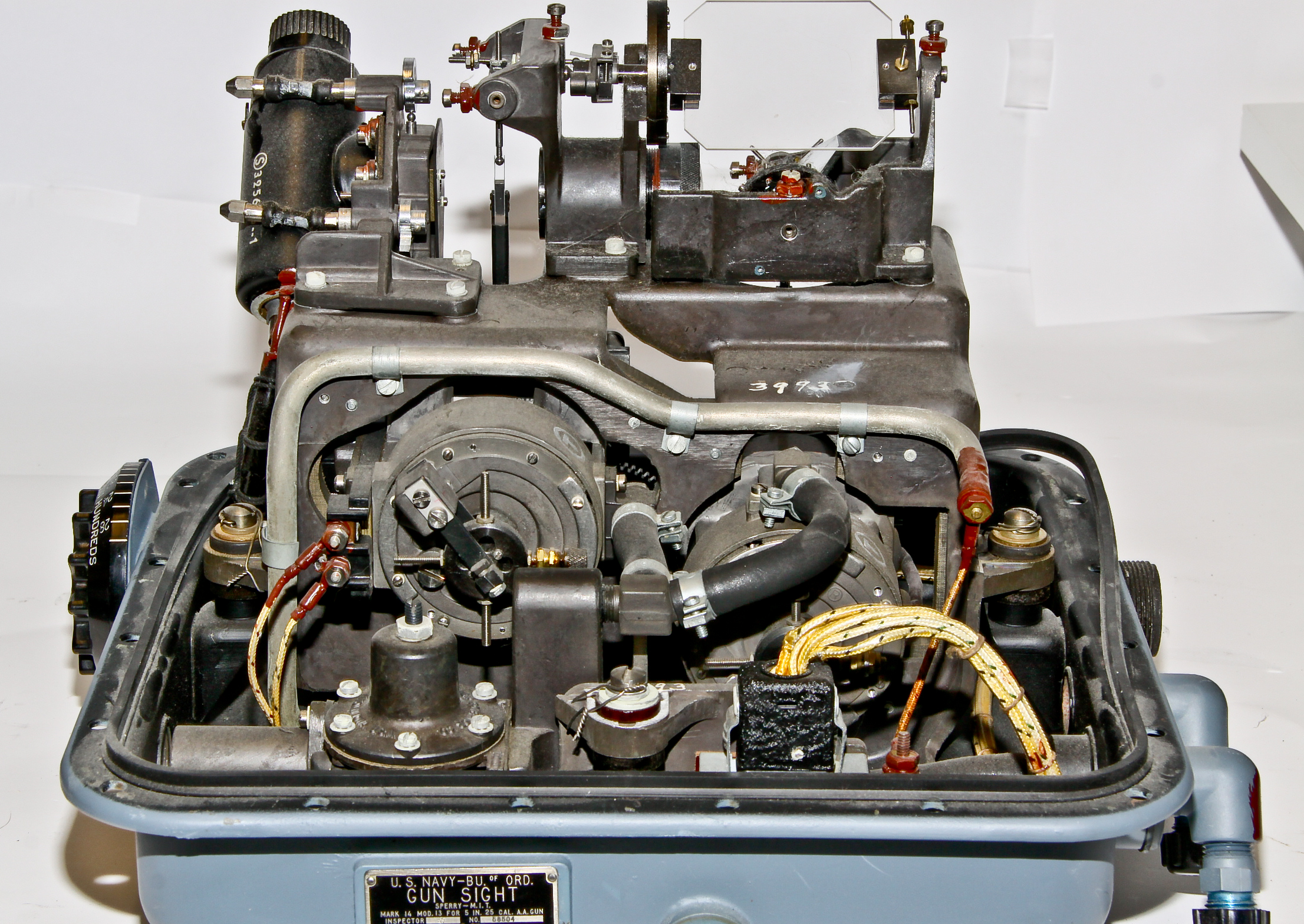
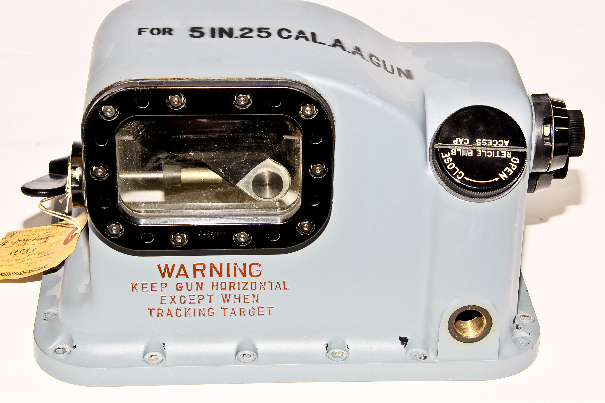
This World War II bombsight was originally designed by the British (as the Mark XIV bombsight) and first entered service in 1942. It was also made by Sperry, who made improvements. It was used in the B-25 and deHavilland Mosquito bombers. There is a separate sighting head (with attached gyro), which I do not have, that communicated to this computing element. The attachment between the two devices was mechanical (flexible cables). The computation was performed mechanically (with much done pneumatically). A set of replaceable cams were provided which adjusted the unit for each type of plane. Shown on left is an old illustration of the complete system including the sighting head.
We actually are fortunate to have two of these bombsights. One is more complete having its motor installed, while the other is missing its motor (the large hole) but is much cleaner and has its shock mount frame.
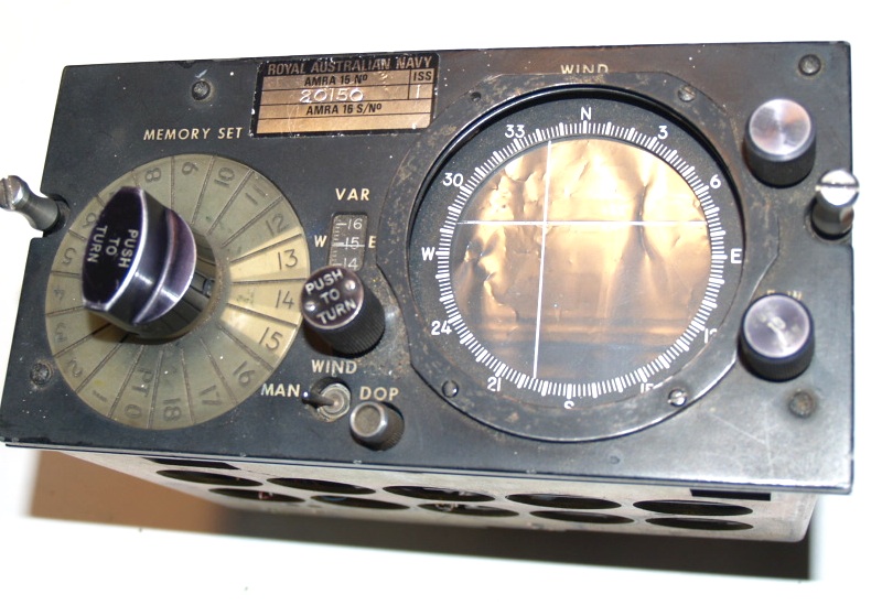
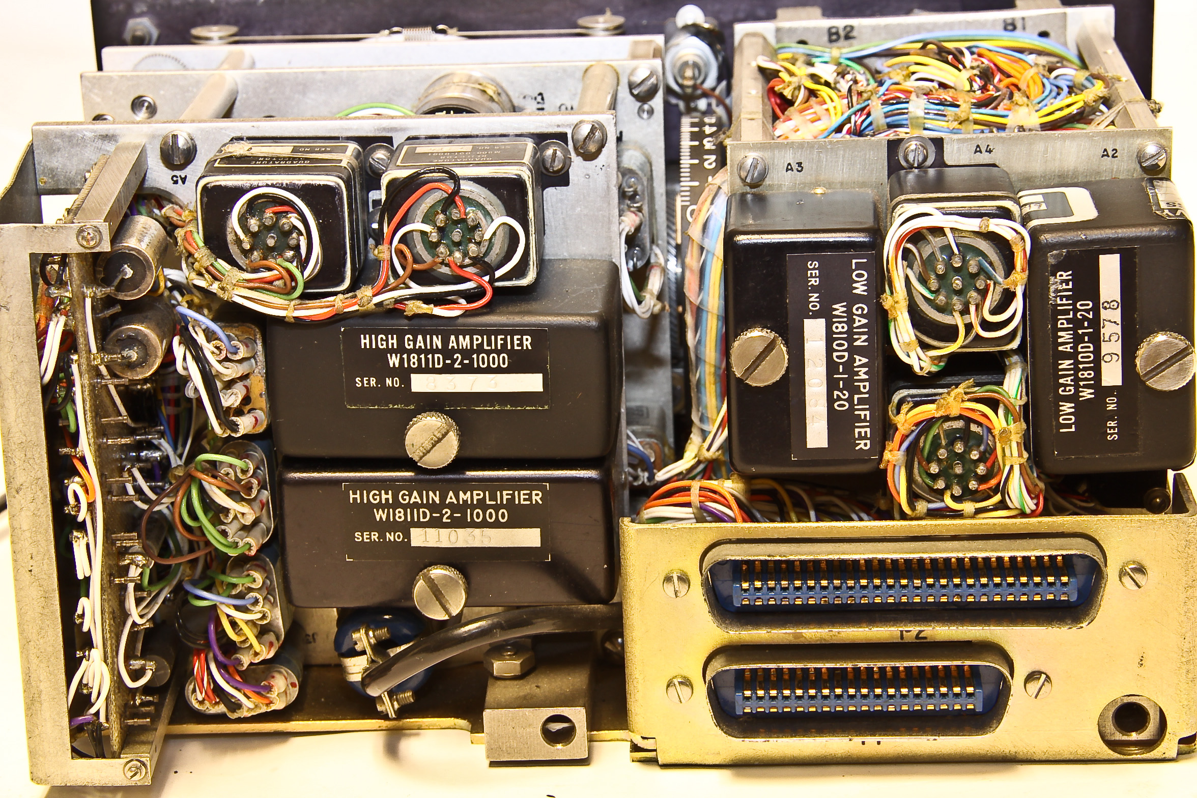
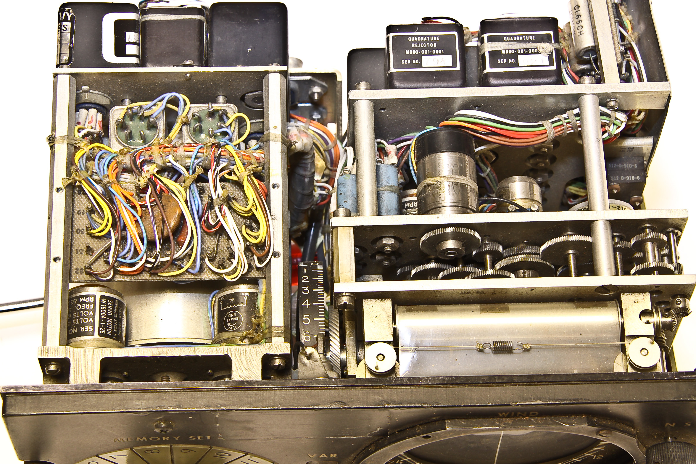
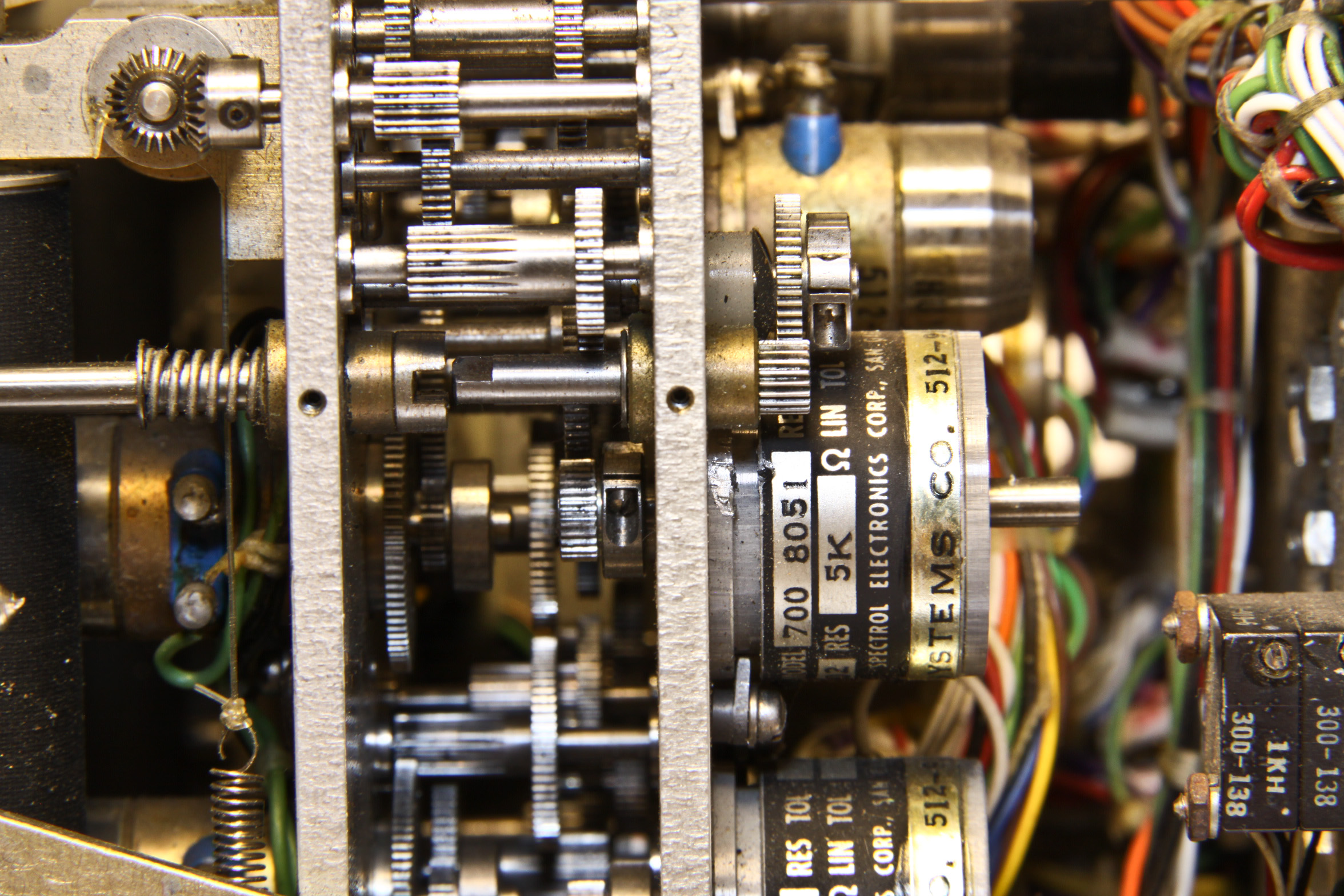
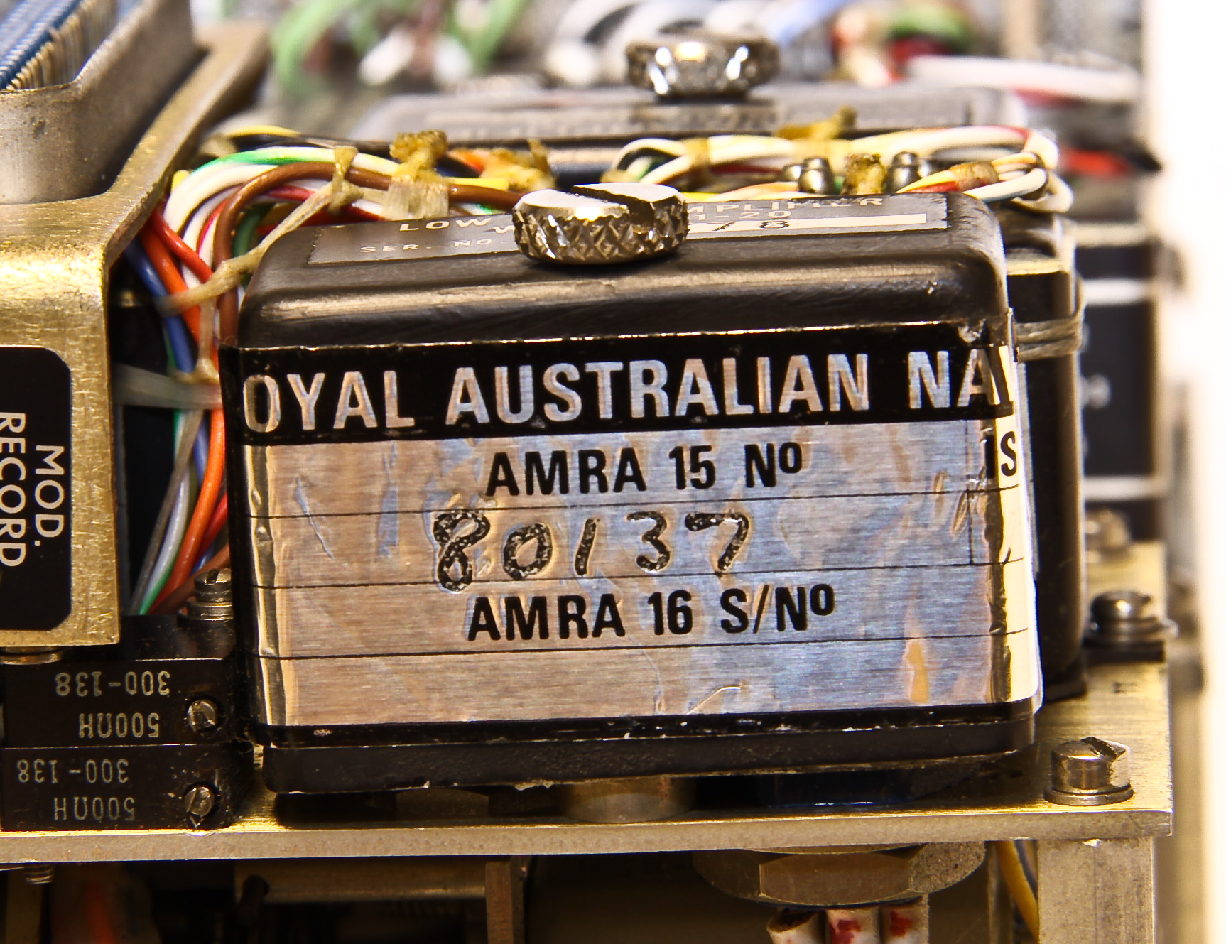
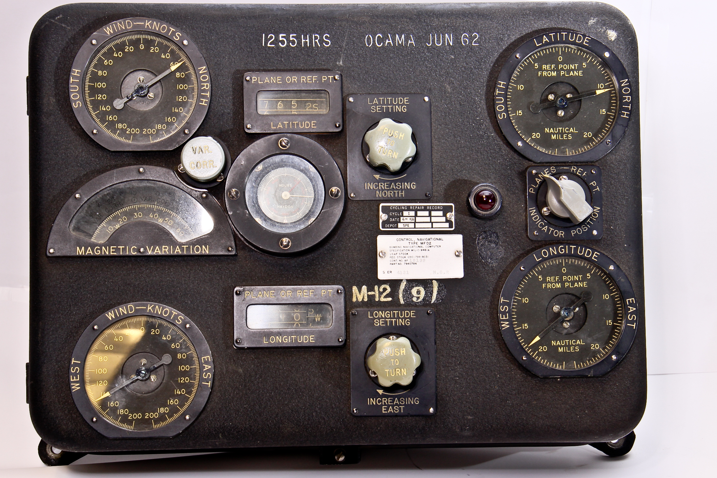
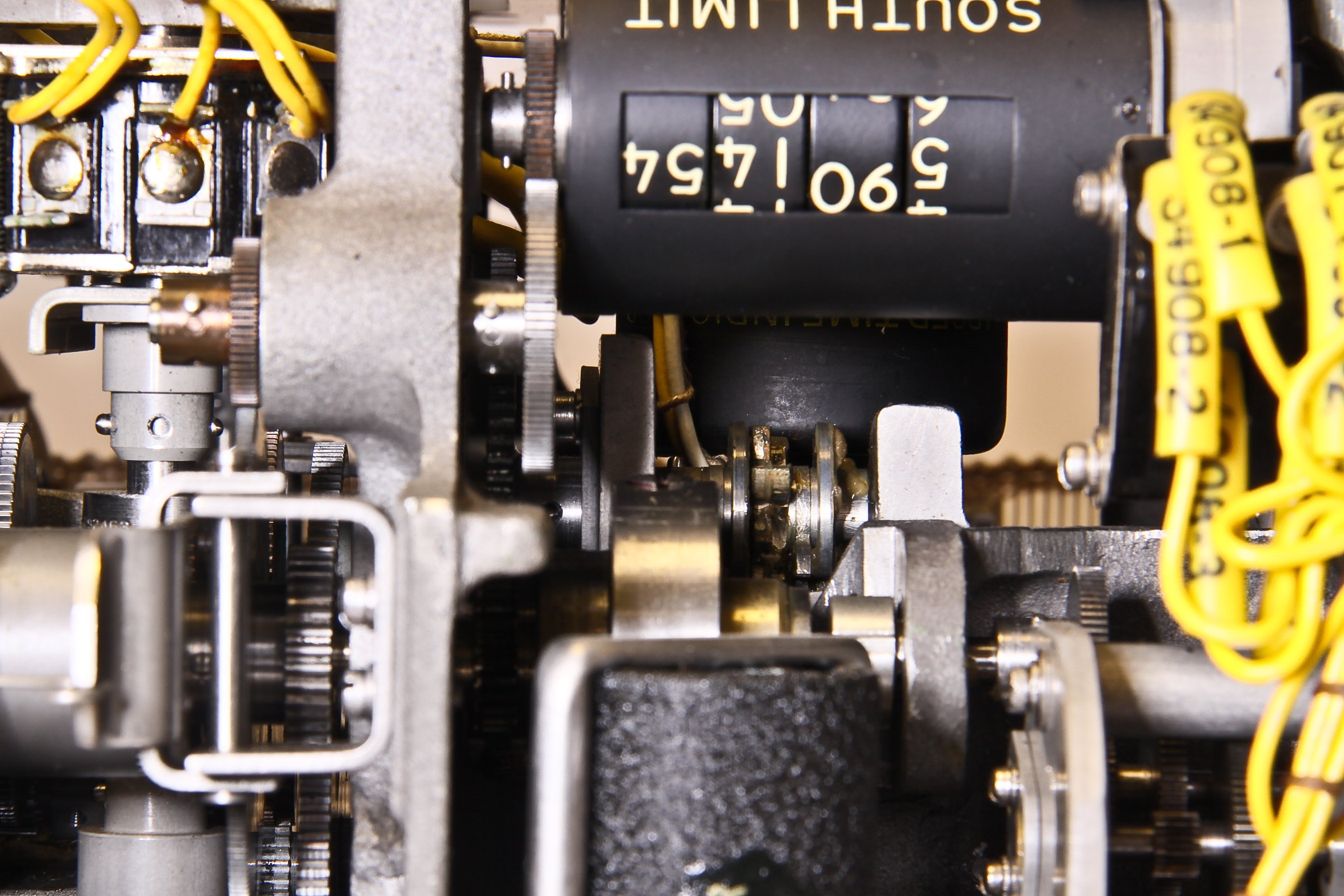
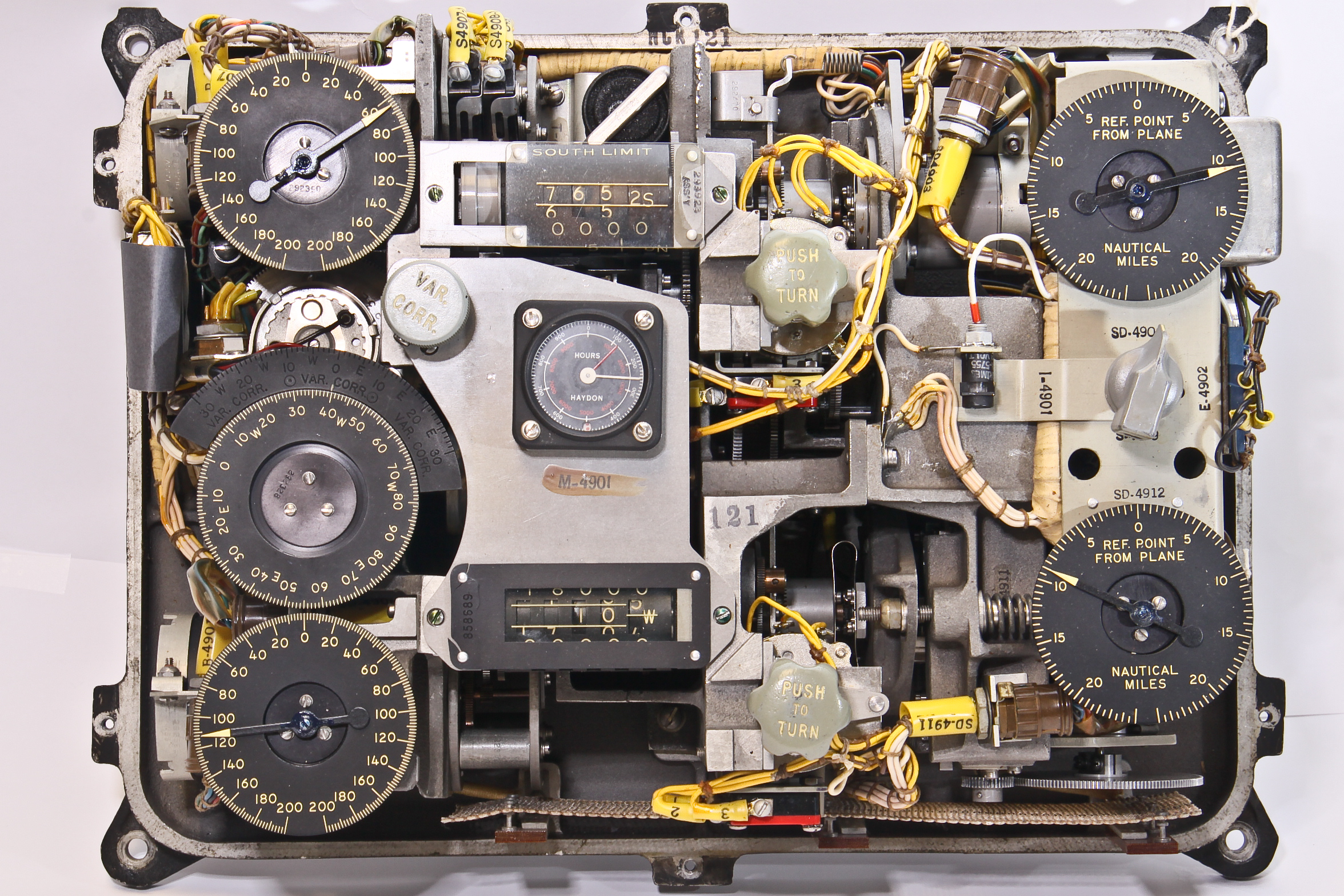
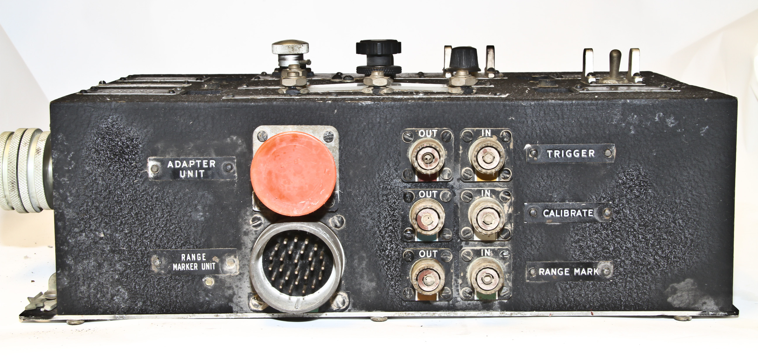
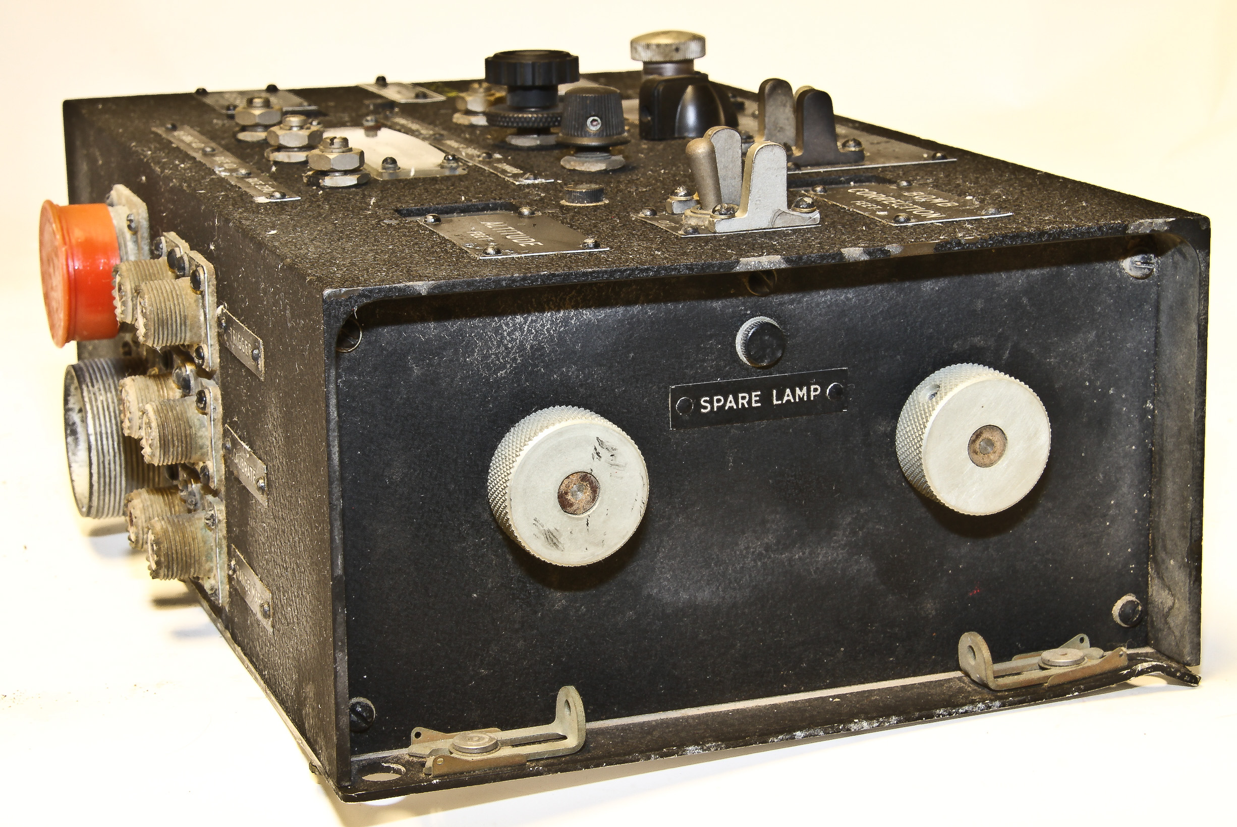
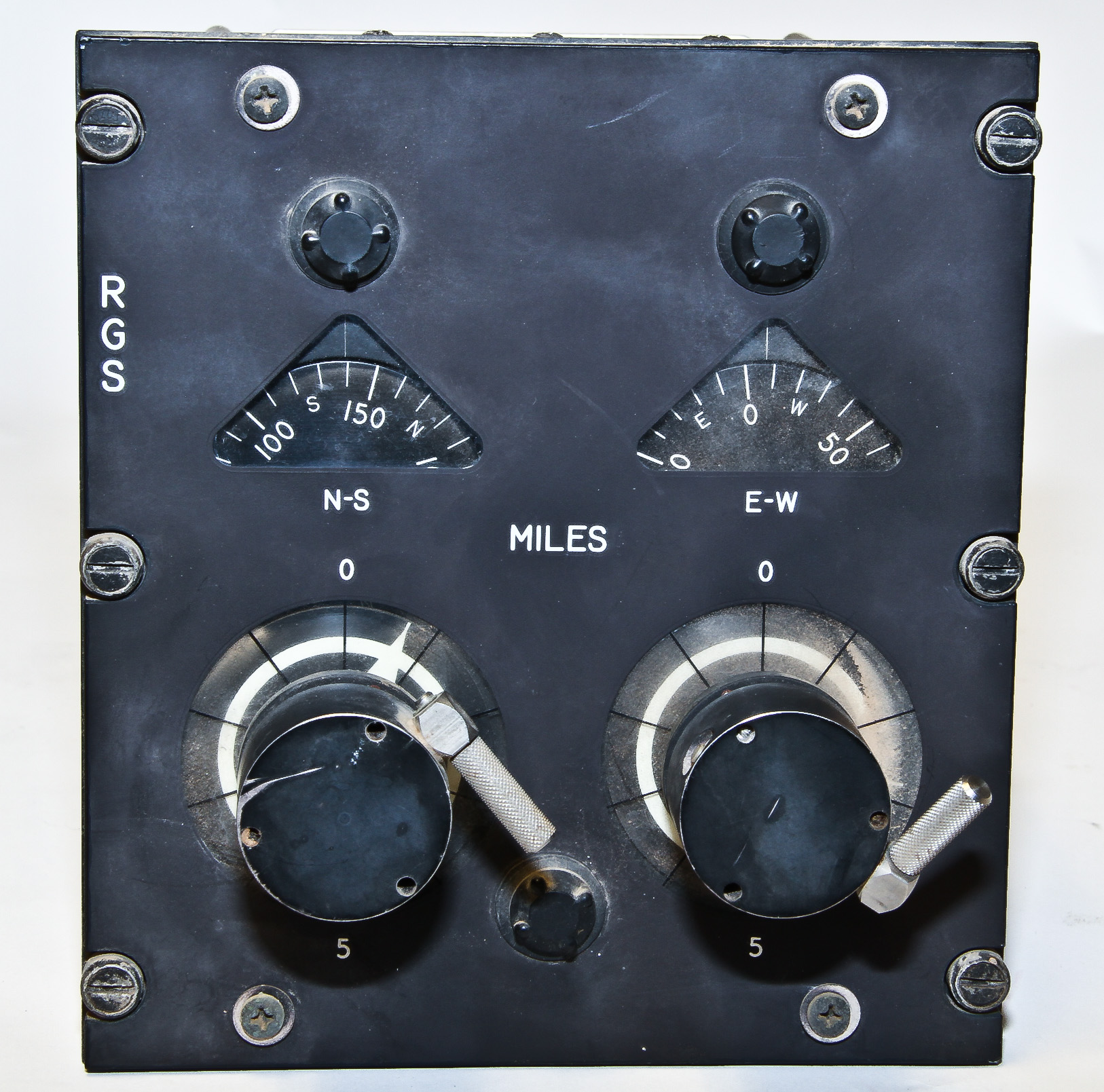
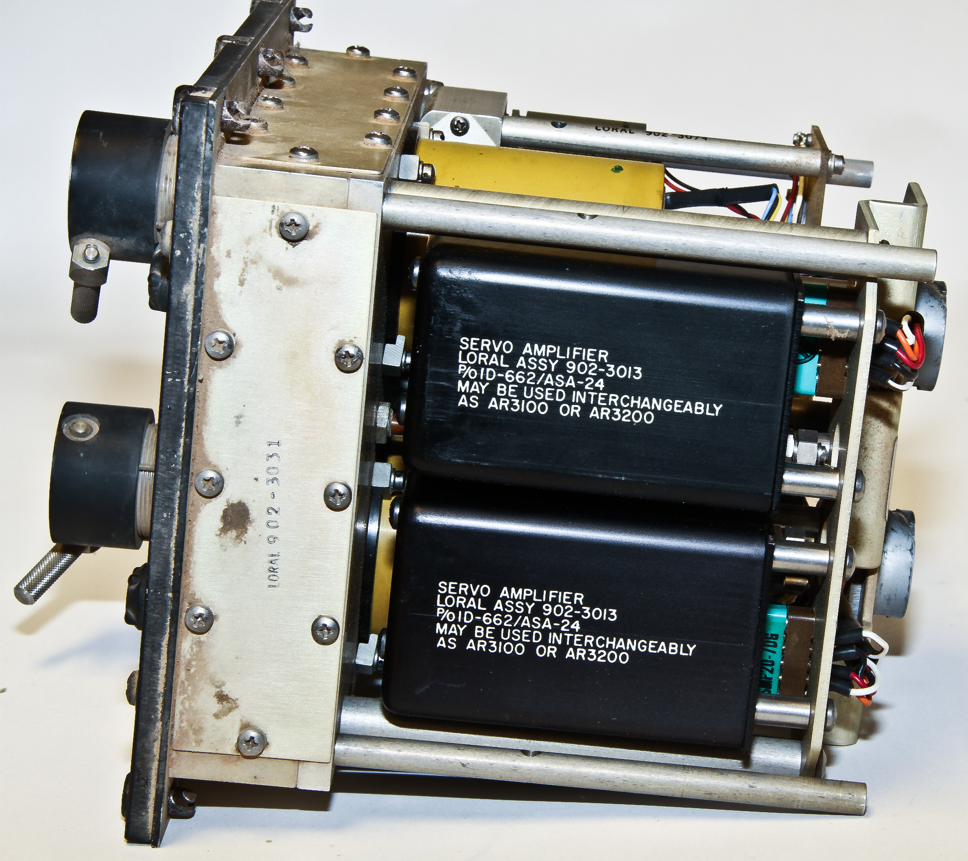
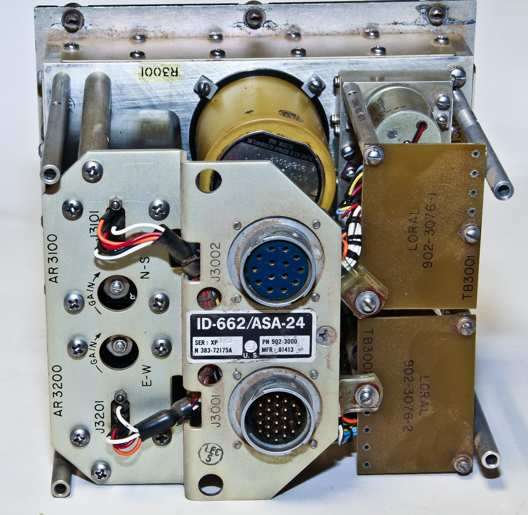
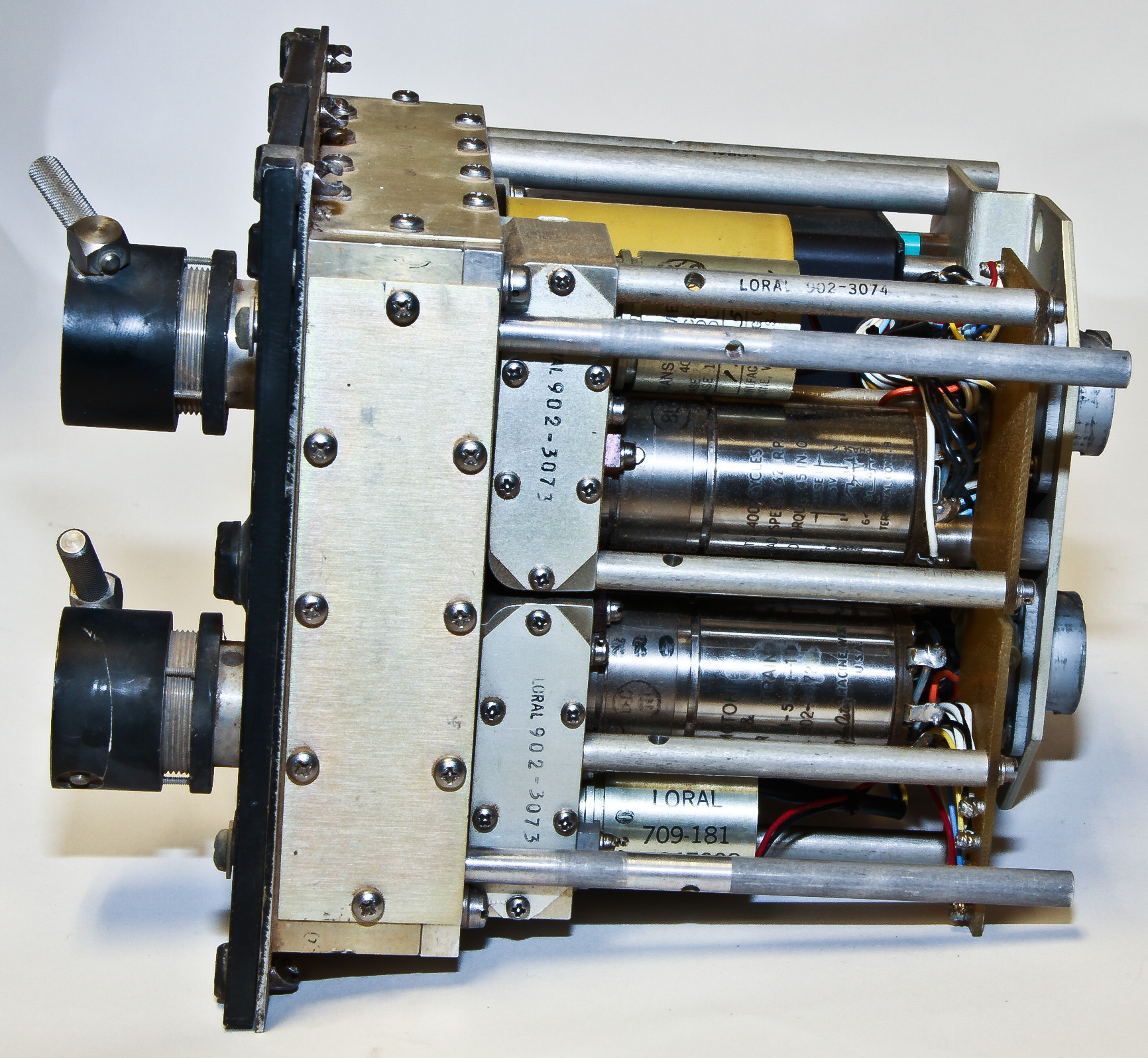
This is a navigation related computer and display apparently made for the Royal Australian Navy (see the label) by Huyck Sysyems (label on the side, not shown). It is filled with a variety of electro-mechanical components (gears, servos, electrical clutches, potentiometers, etc.) as well as some electronics (high-gain and low-gain amplifiers, quadrature rejectors, and a lot of resistors and capacitors).
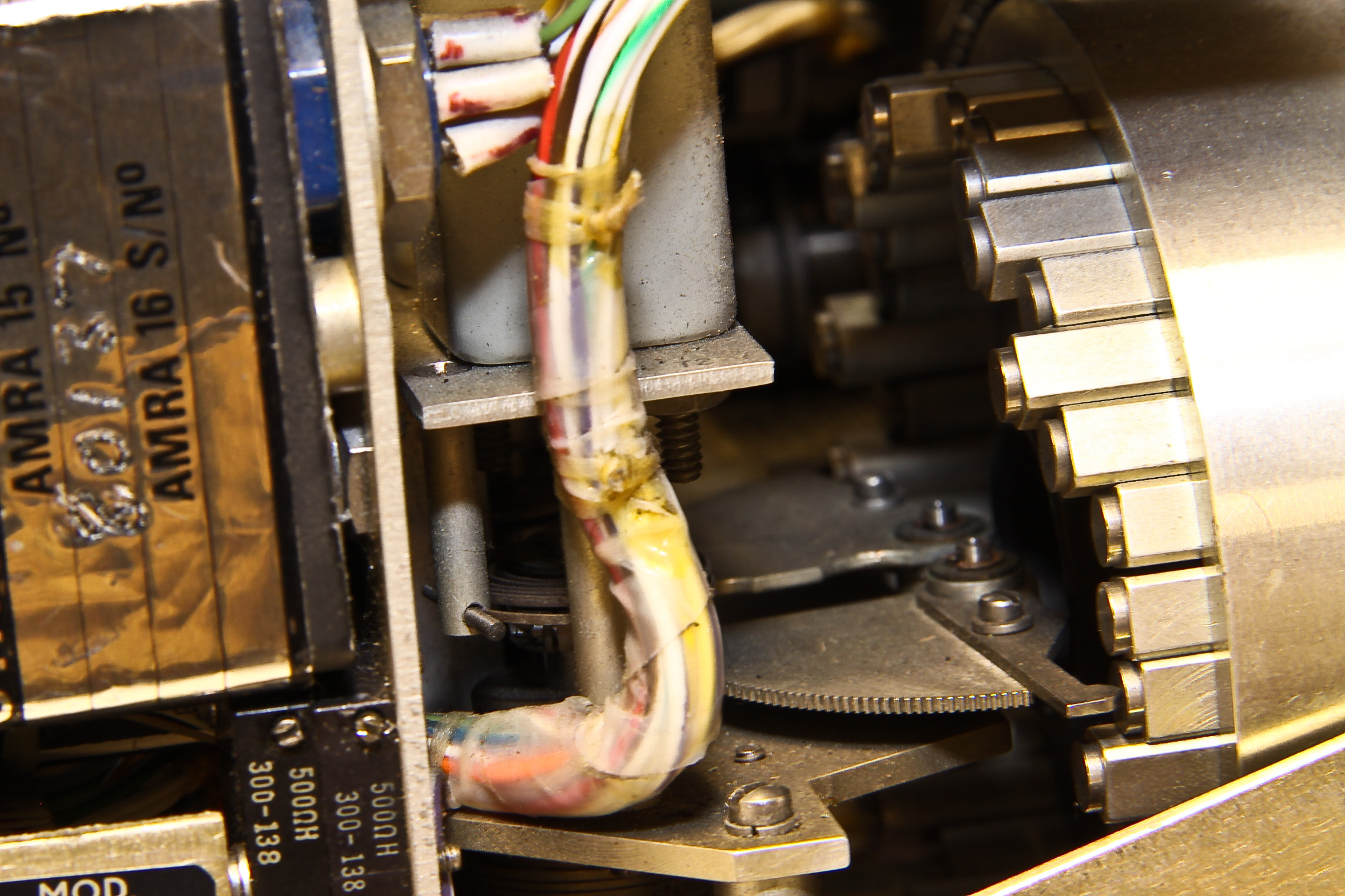
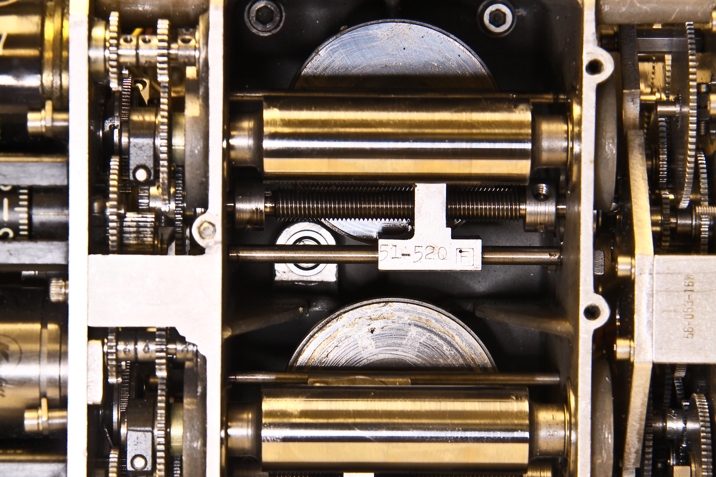
Of particular interest is a 19 position mechanical analog memory. The "memory set" knob rotates a carrier with two cams for each of the 19 positions. The selected cams each move an arm which moves an electrical resolver to provide the electrical value for the position. The back of the carrier and its cams and the sensing arm are shown in bottom left picture (there is a cam and arm on both sides if the carrier). What is not shown is a mechanism at the front of the carrier where two servos engage the two screws that adjust the length of the selected cam. This is how the memory values are set.
Exactly what this device does is not clear. The NS and EW knobs on the right move the crosshairs on the display and set values via potentiometers. When not being set, the crosshairs are driven by the computing mechanism. Also, the display is presented in degrees (not NS-EW) and is labeled "wind". Based on my piloting experience, this seems too complicated (oe weird) just to be indicating wind direction. A center knob sets a variance, but variance of what to what? Again, when not being set, the variance display is being driven. Below this knob is a switch (not easily seen) labeled "wind" with positions "man" (surely manual) and "dop" (Doppler?).

This is a navigation computer used in the RB-57, the C-135, the F-100, and the RF-101.
(Here is a site summarizing the U.S. military equipment designations, such as AN/ANS-7).
The ANS-7 first flew in the late 1950's. It was made by the Ford Instrument Co. (not affiliated with Ford motor companies). At the time Ford was one of the premier manufacturers of electro-mechanical analog computers, including the most impressive monster: the Mark I, which weighed over 3,000 lbs. (More on the Mark I below).
Figure 2 is a closeup of two of the three disk integrators (as described in the intro to this page) contained within the ANS-7.
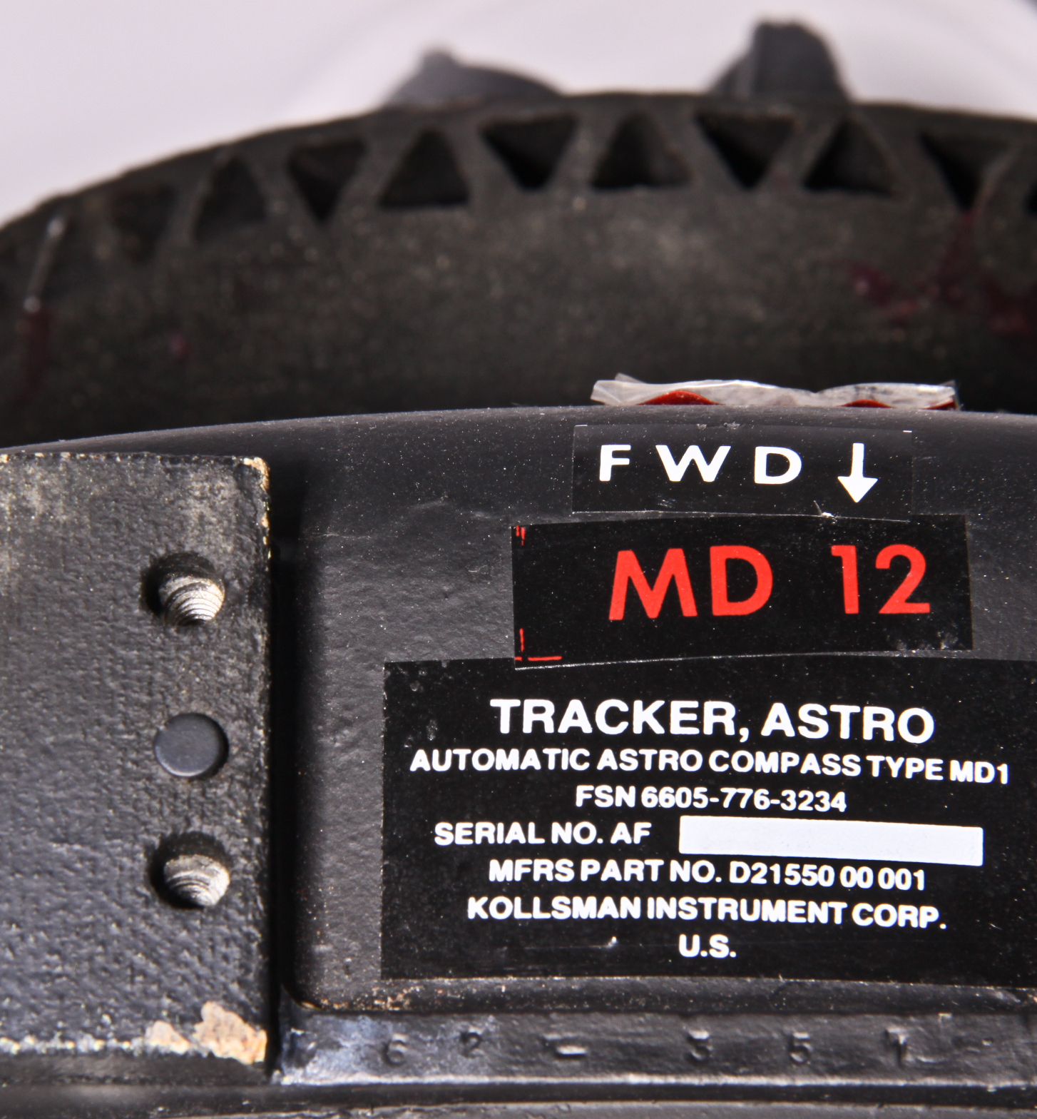
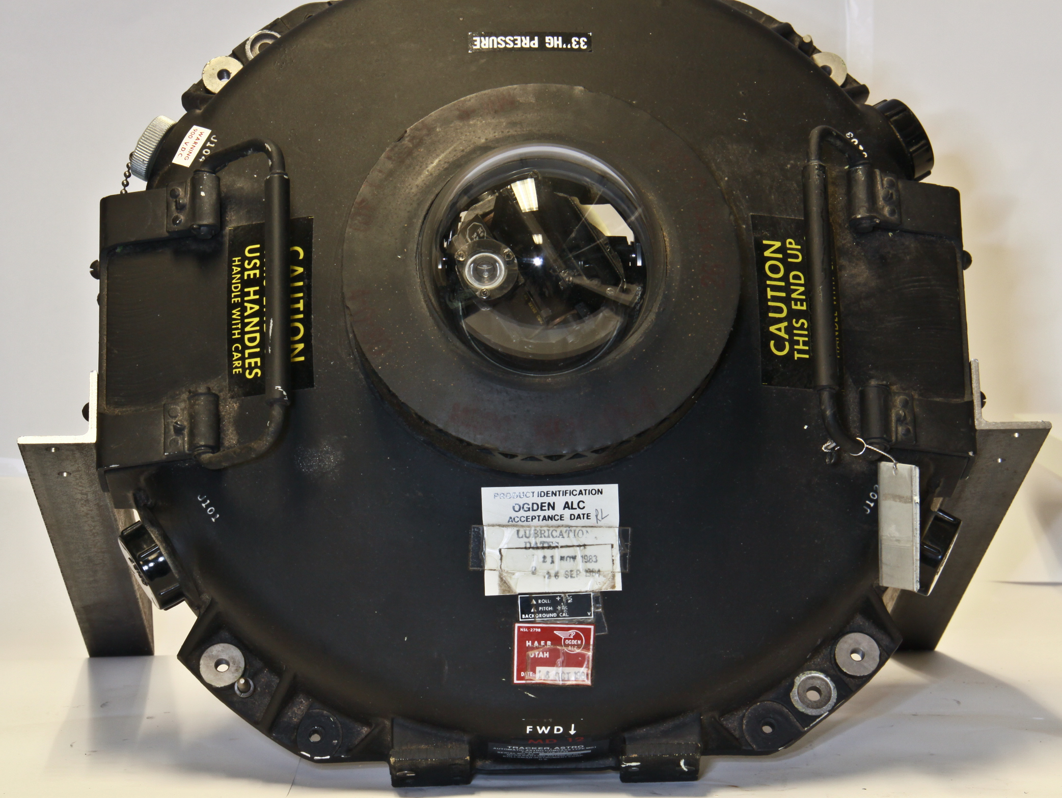
Before GPS, a primary navigation method for ships, aircraft, spacecraft and missiles was celestial tracking, also known as astronavigation. The basic approach is to sight on the sun or a particular star and calculate the position of the aircraft, missile or ship from the sighting angles to the star. The calculation is based upon highly accurate data about the positioning of the sun and certain reference stars at various time and locations. For modern applications, the star tracking location is used to calibrate and update an inertial navigation system.
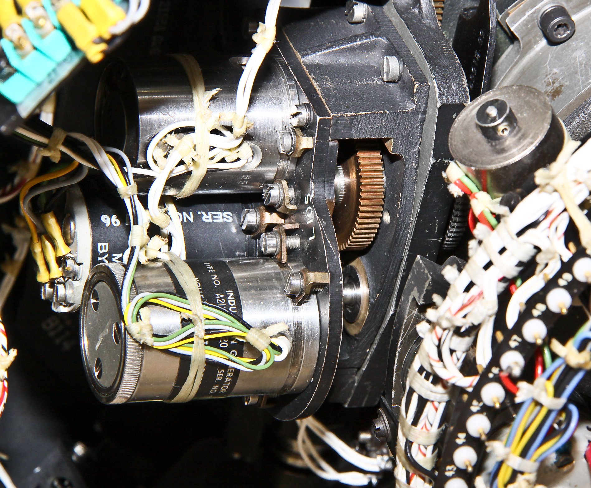
Early Air Force aircraft such as early B-52 bombers relied on a human using a sextant through a bubble in the top of the plane. Some time in the late '60s, manual sighting was replaced on the E and F models by this automatic astro tracker mechanism and its associated analog computer. At some point, the astro navigator was replaced by GPS. Our device has a maintenance tag dated 1983, so the system was used at least until then.
Similar "star trackers" were and are used on many other planes such as the SR-71 and RC-135 reconnaissance aircraft, the B-58 bomber, and the P-3 Orion patrol plane. Of special interest is the fact that the most modern USAF plane, the B-2 bomber, still has a automatic star tracker navigation system. Many missiles, including some currently operational ones, also use automated start tracker navigation: the Polaris, Poseidon, Trident, MX, SM-62 Snark and the AGM-28 Hound Dog, and others.
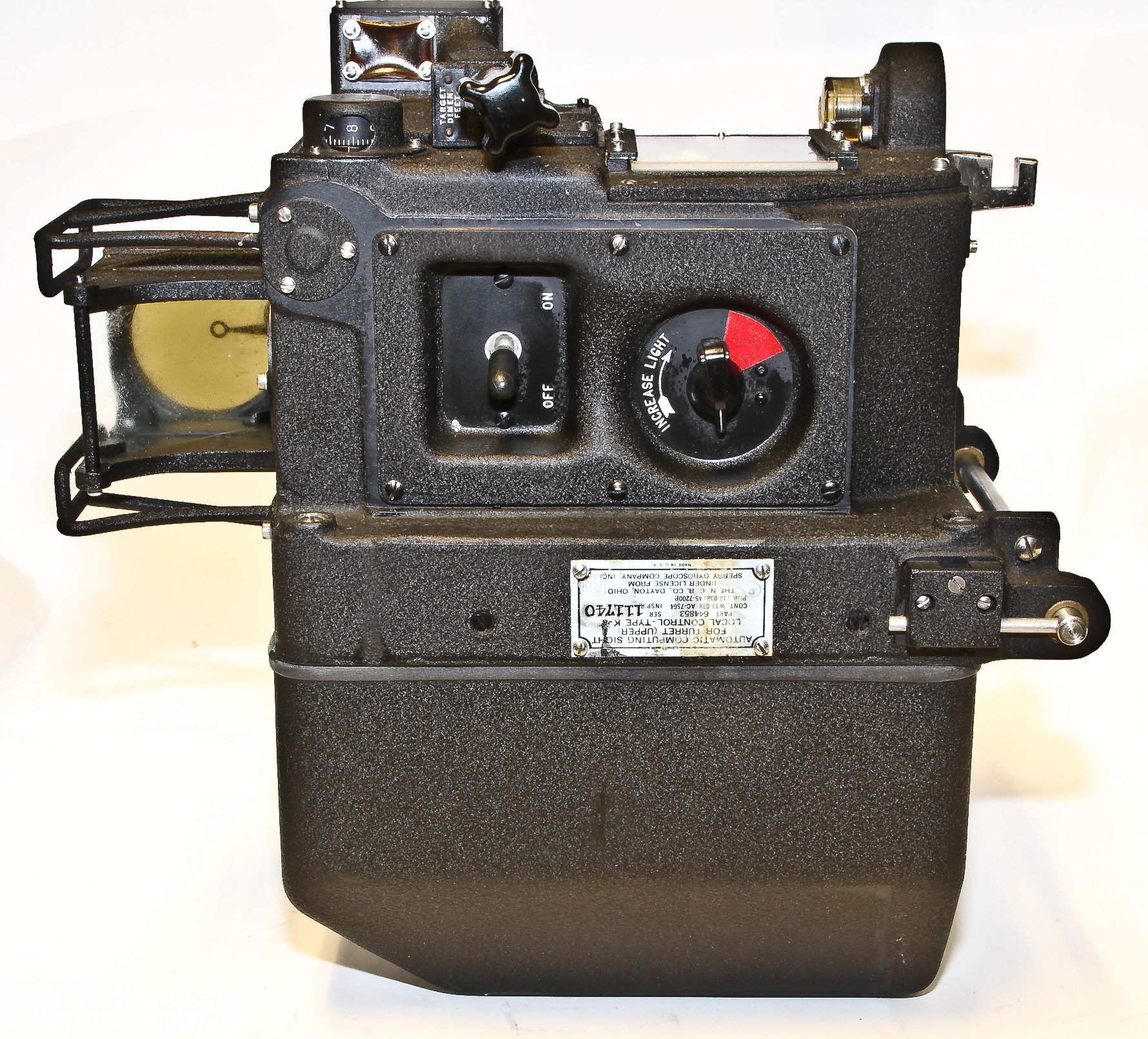
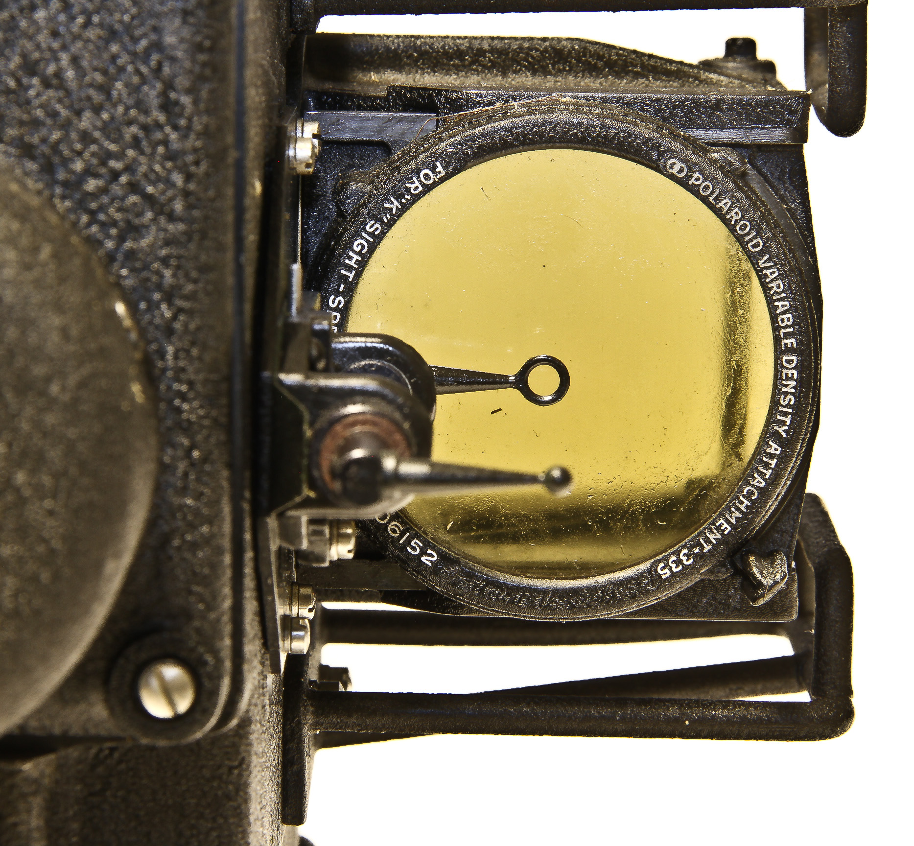
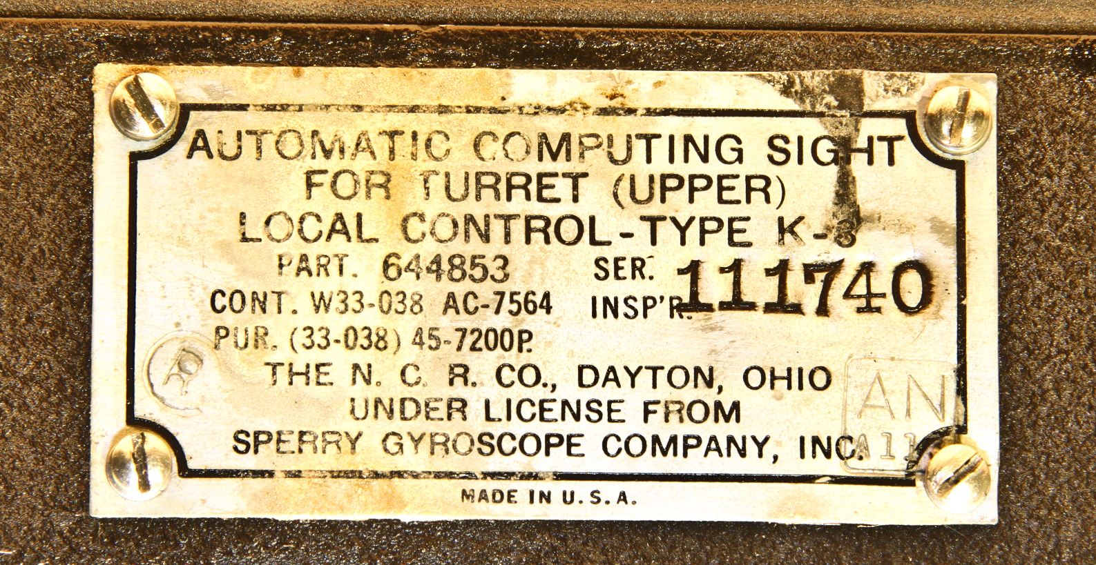
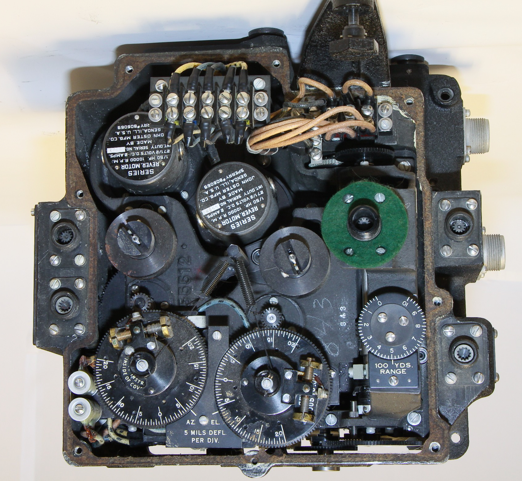
The K-3 is a computing gunsight used in used in Sperry upper gun turrets used on the B-17 bomber. The K-4 is the same device with a different mount used in the Sperry lower gun turrets on the B-17. Figure 1 shows our two K-3's plus a computing element from a third. The other pictures show various views of these devices. Figure 9 shows a page from the Gunner's Information File illustrating the lower turret with the K-4 sight right in the middle.
The gunner inputs range information by estimating the size of the plane and adjusting its image in the attached optical sight so that the image fits withing reticles. The gunner then tracks the target with the optical sight by moving the K-3 (mounted on a movable head) keeping the plane image centered in the reticles. The sight movements cause the computing unit, which, based on the range information and built-in ballistics data, to calculates the deflection, or lead, for aiming the guns and moves the turret accordingly.
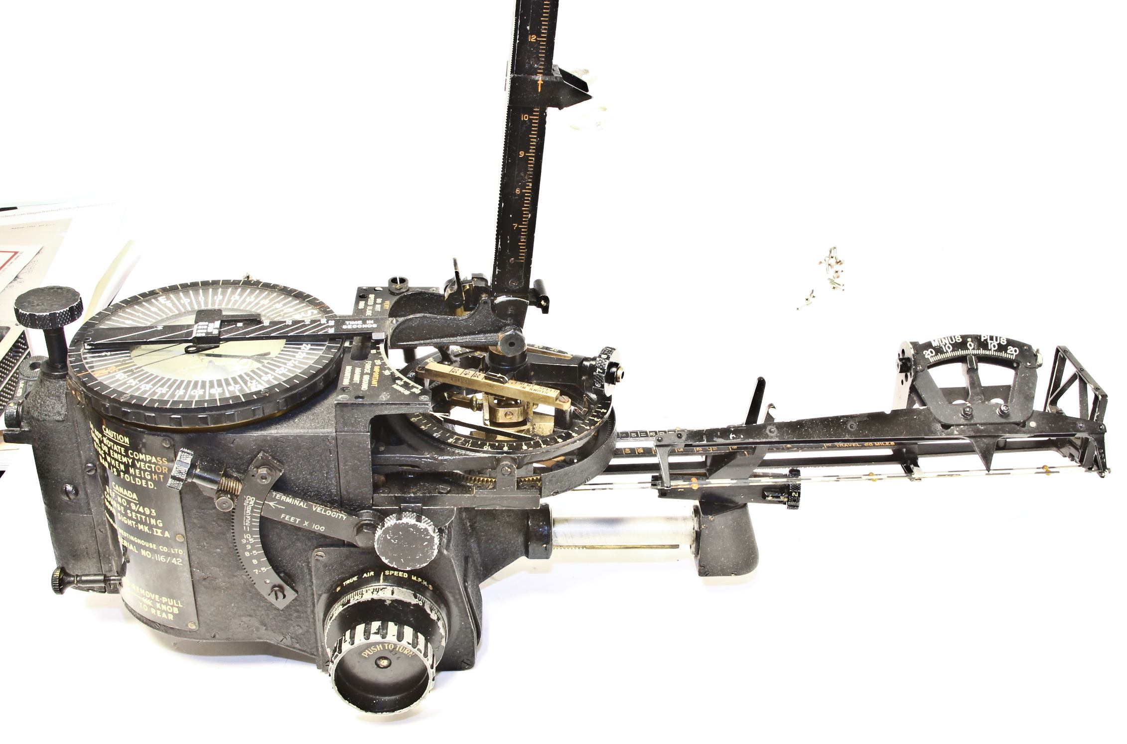
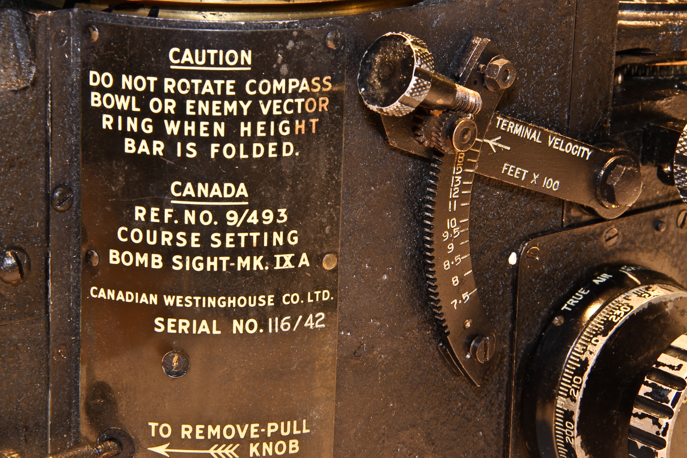
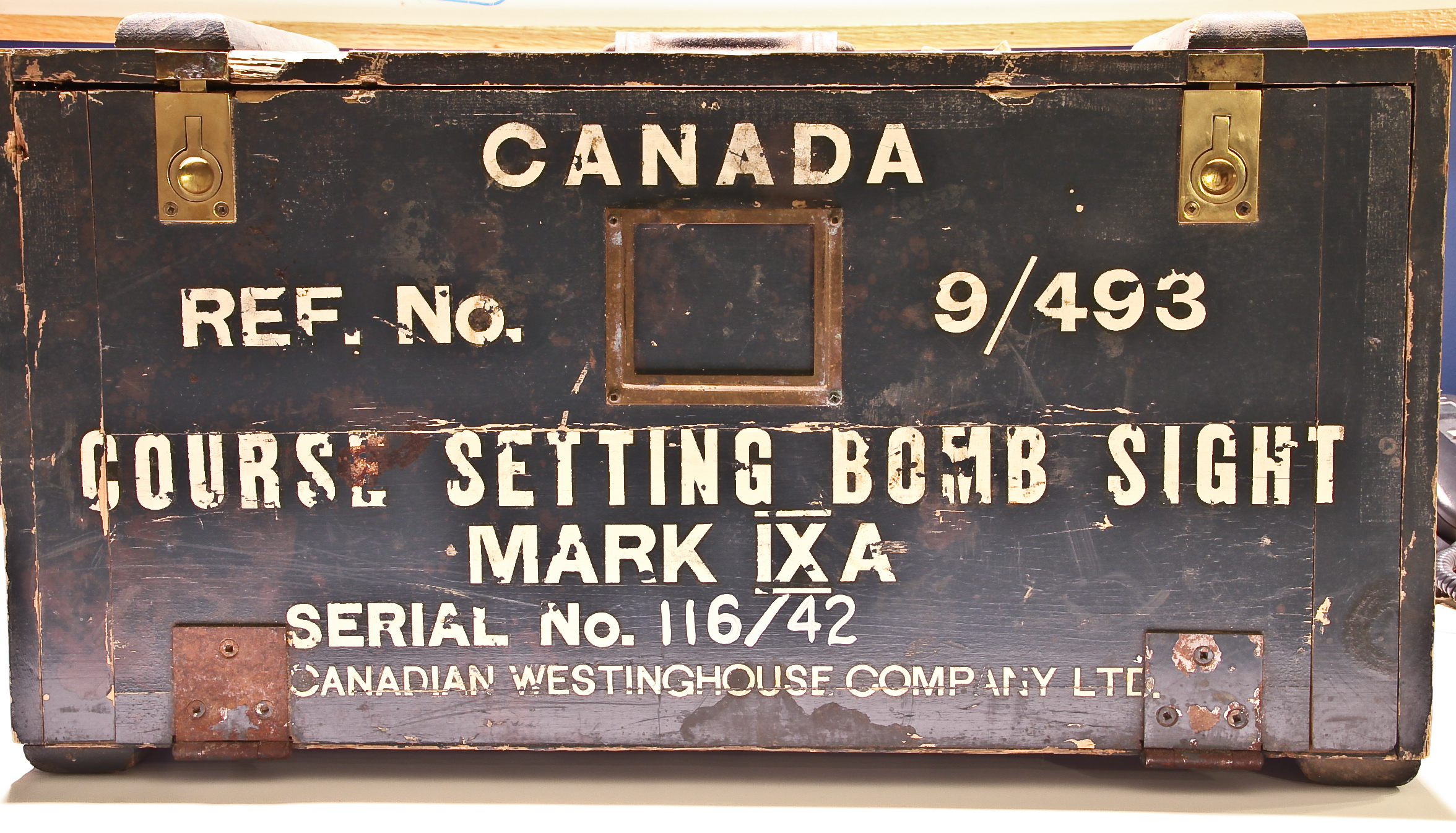
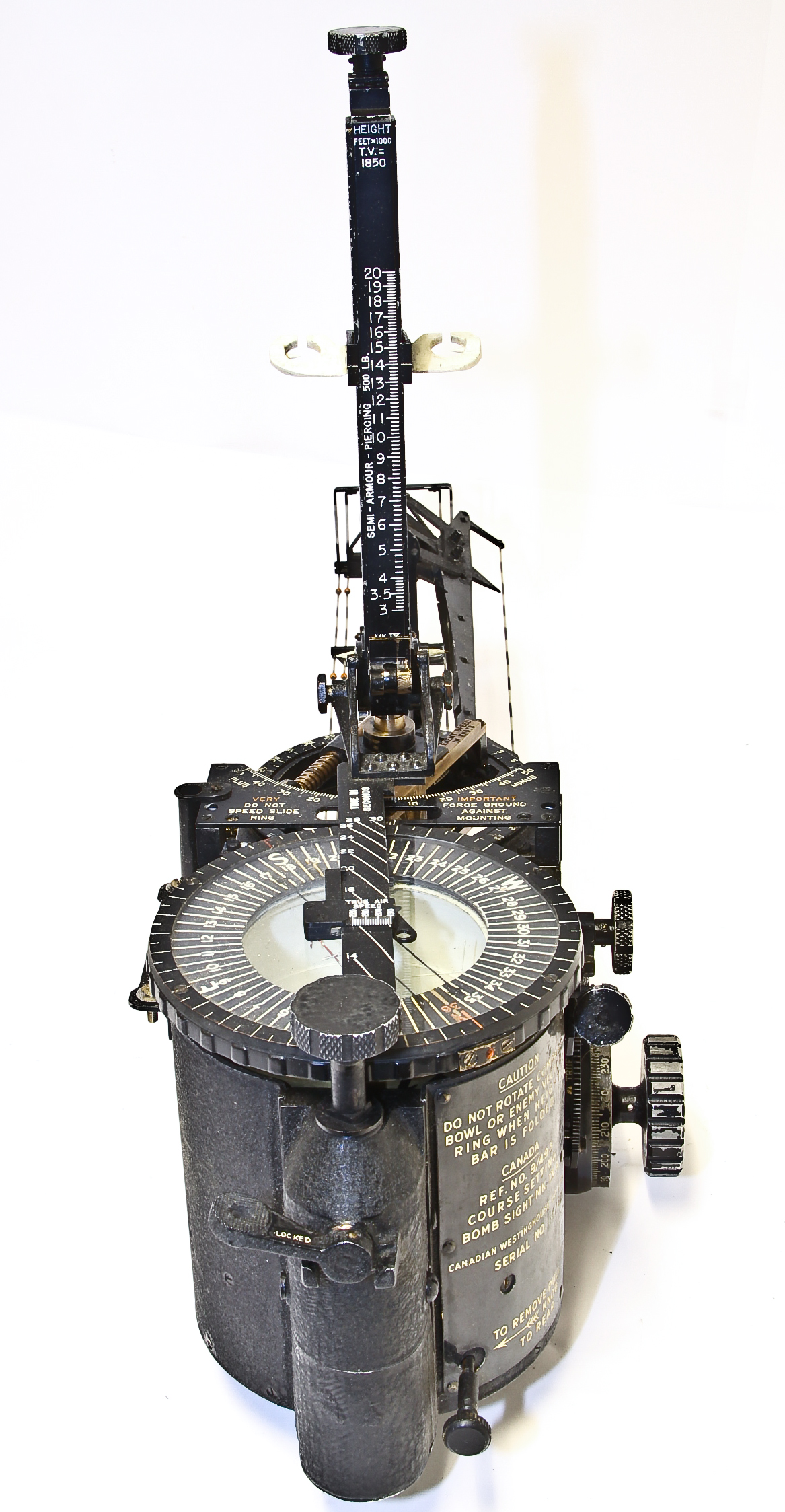
The British-designed RAF Mark IX bomb sight was first introduced in 1939. It was used on Canadian and Great Britain planes in World War II: in particular Lancaster, Wellington and Sterling bombers, and Mosquitos, Beauforts and Beaufighters fighters. This was an early preset vector bombsight that involved squinting through wires that had to be manually set based on aircraft speed, altitude and bombload. The sight lacked tactical flexibility as it had to be manually adjusted if any of the parameters changed.
Our piece includes its original container (including several accessories within the containers drawers), and clearly was clearly in Canadian in 1942. Our particular version, the Mark IXa, was intended for use in land bombers. However, it has the "moving target" attachment, which was usually being reserved for those planes doing maritime duty, where the ship they were aiming at would be moving.
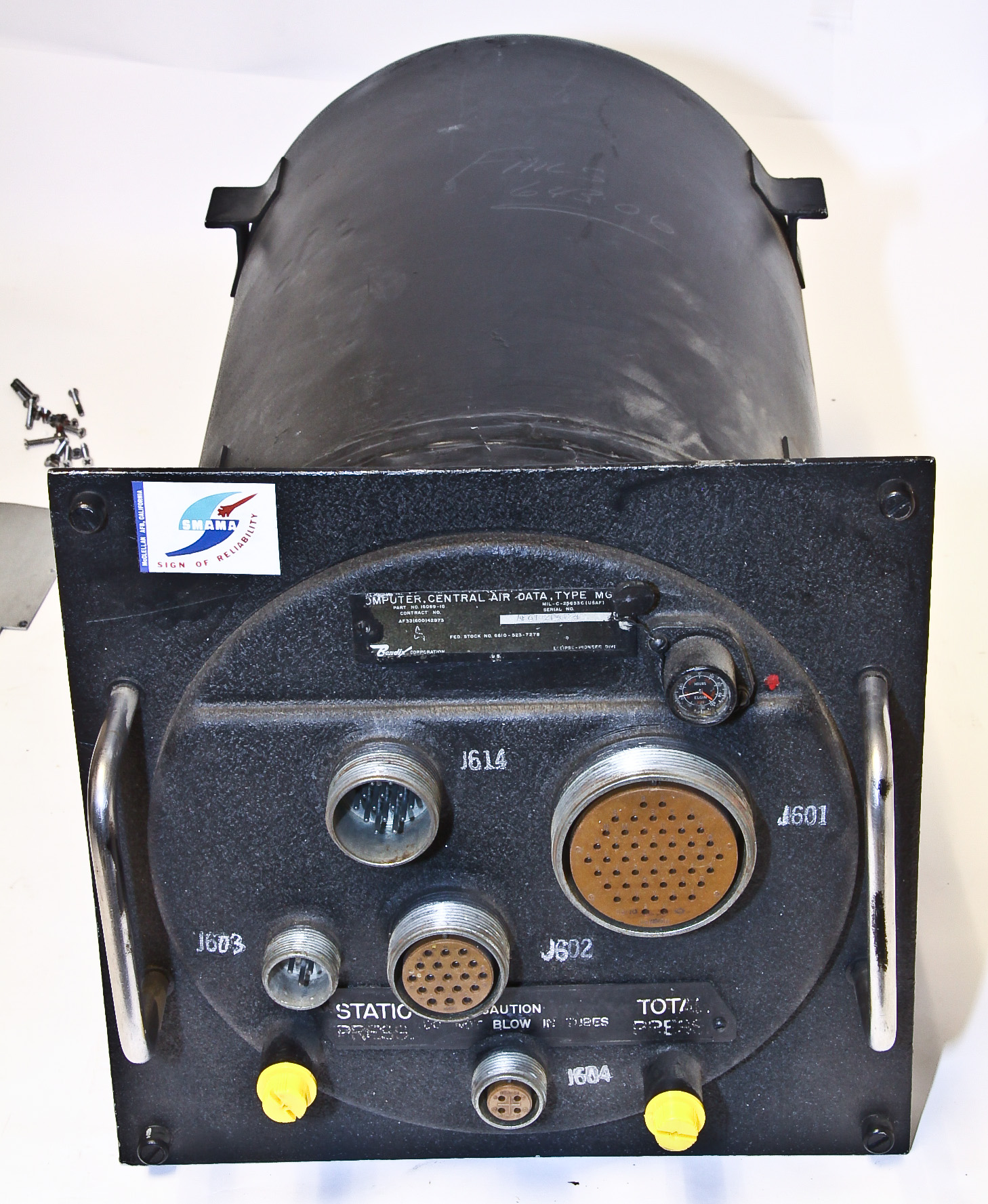
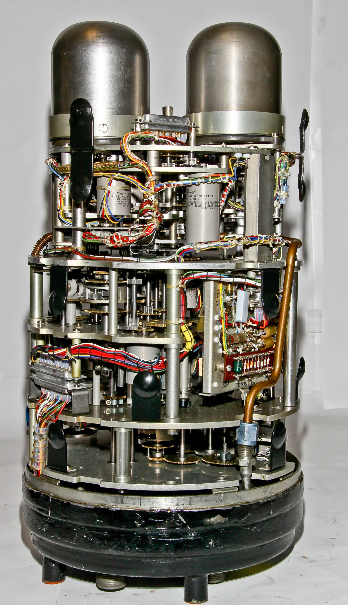
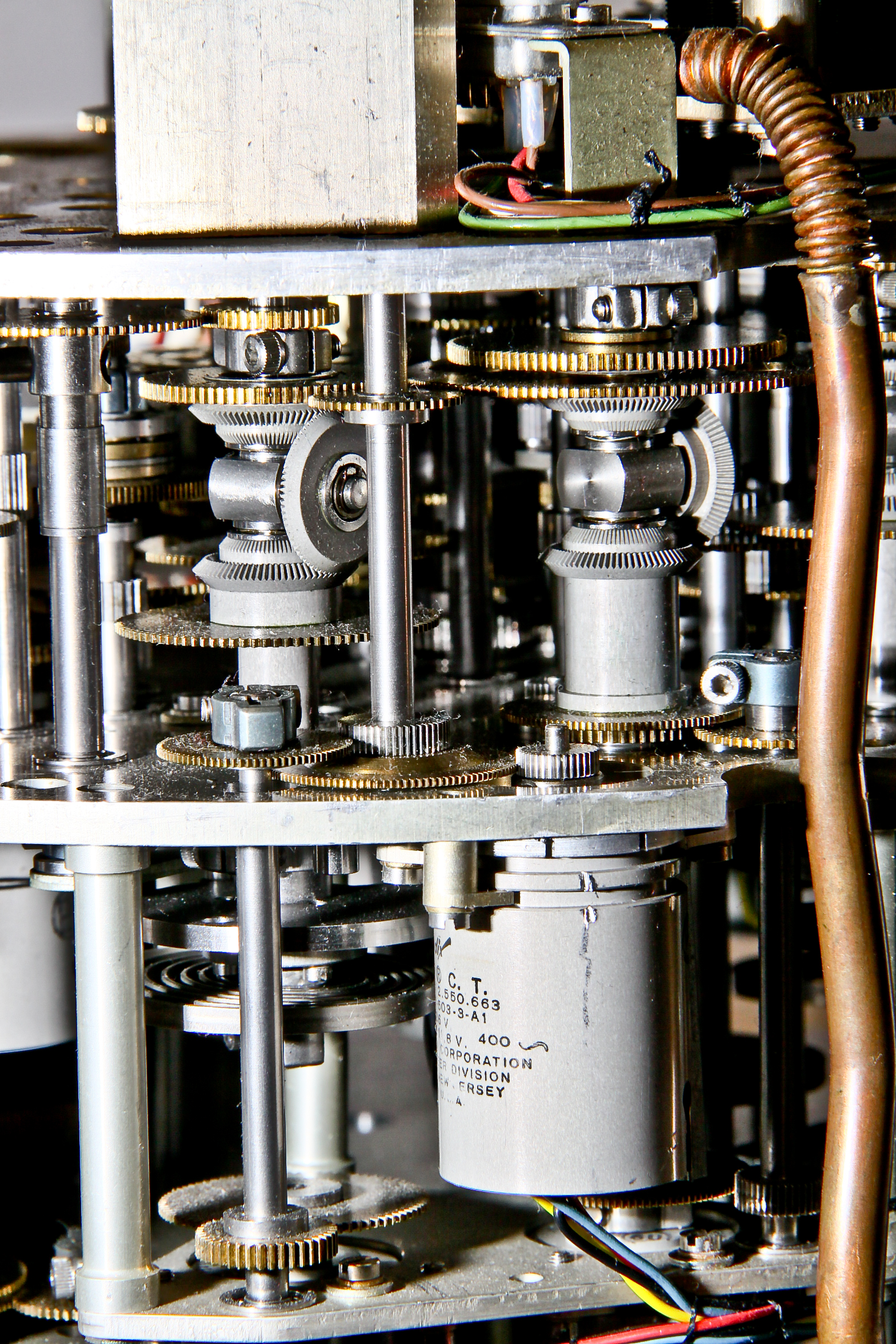
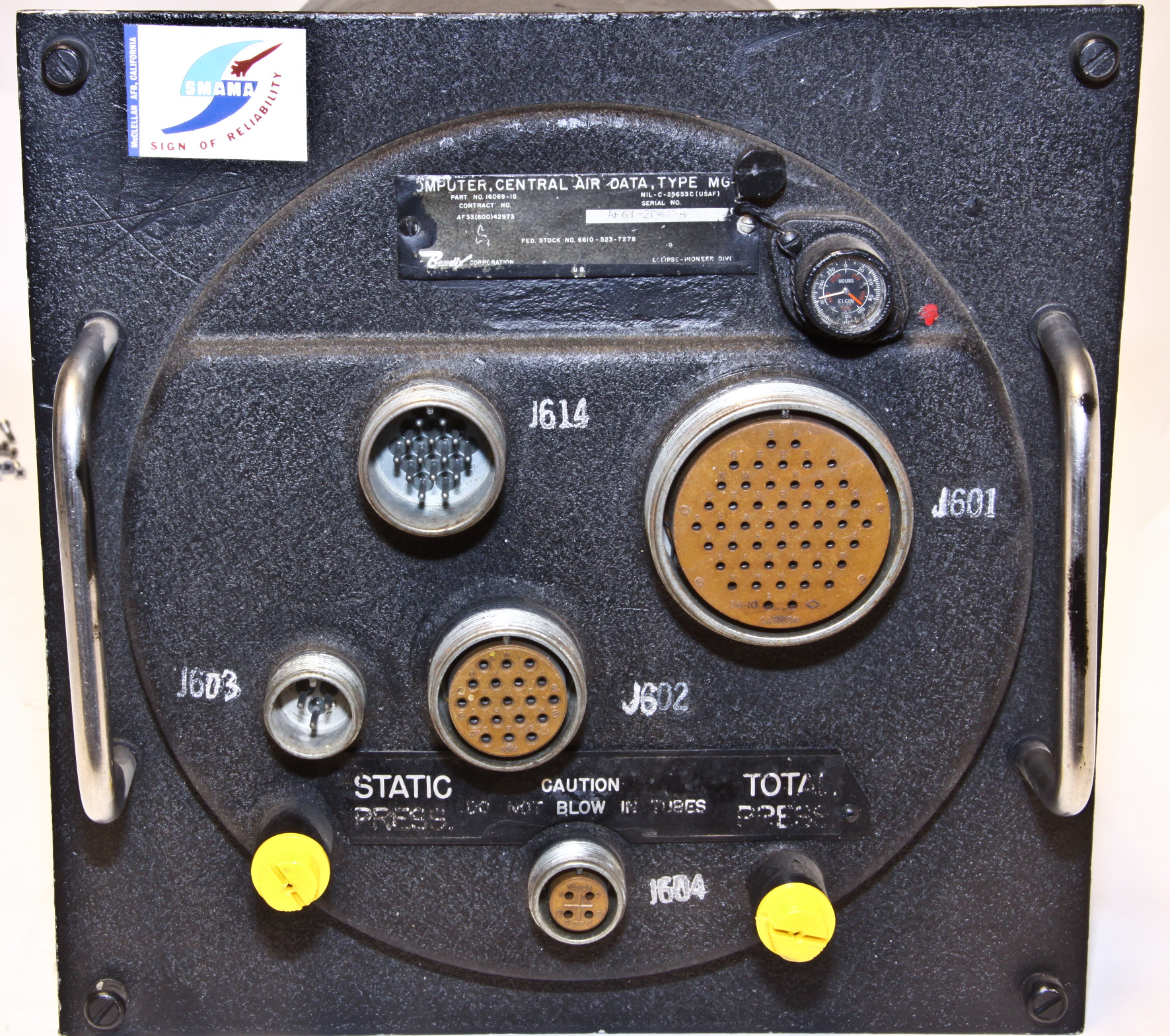
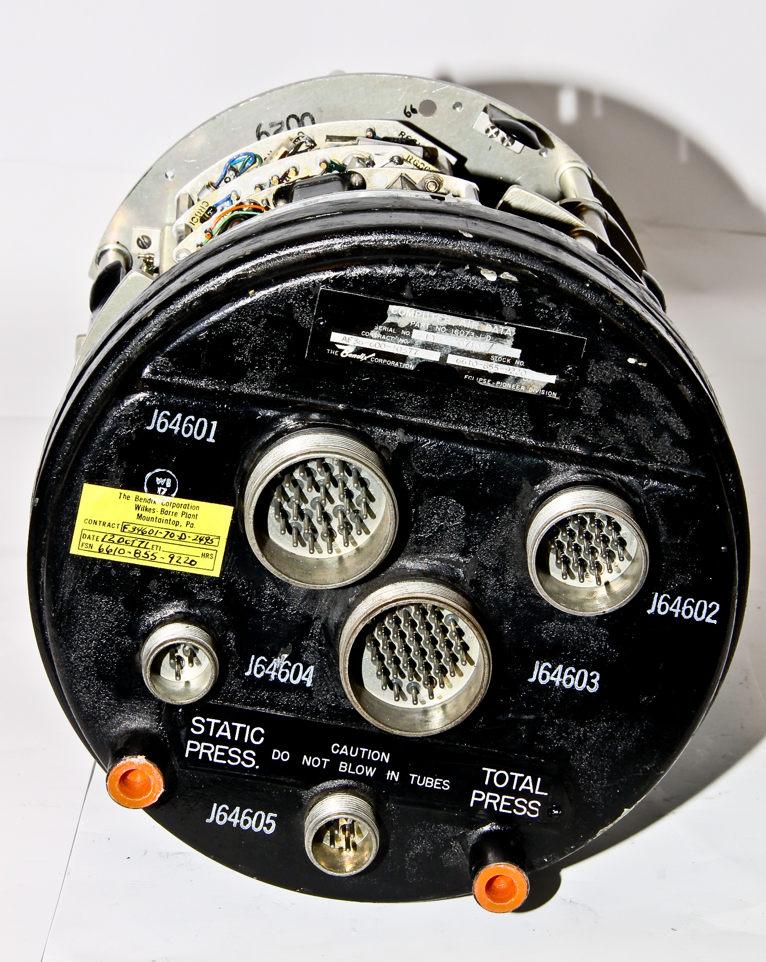
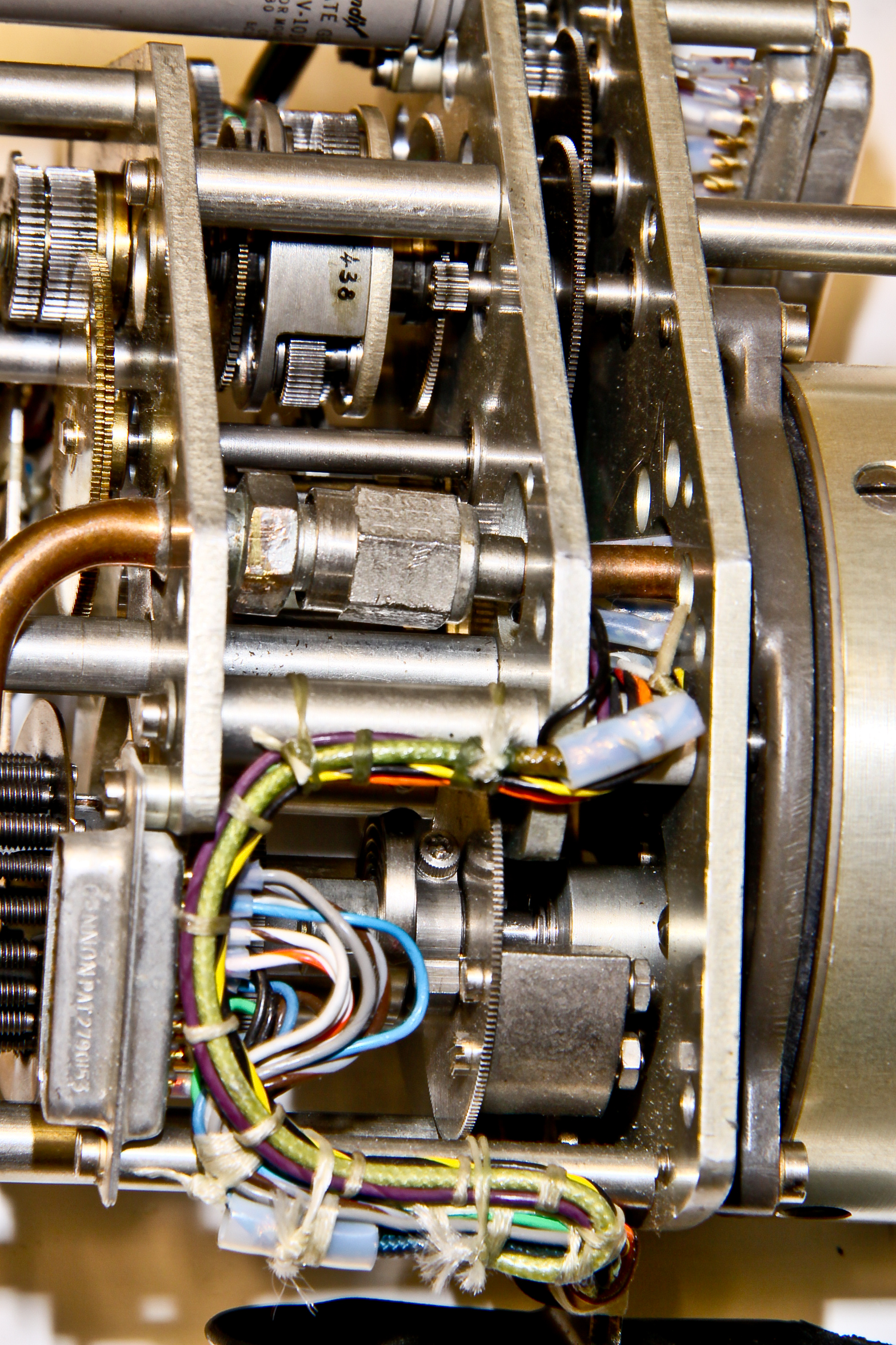
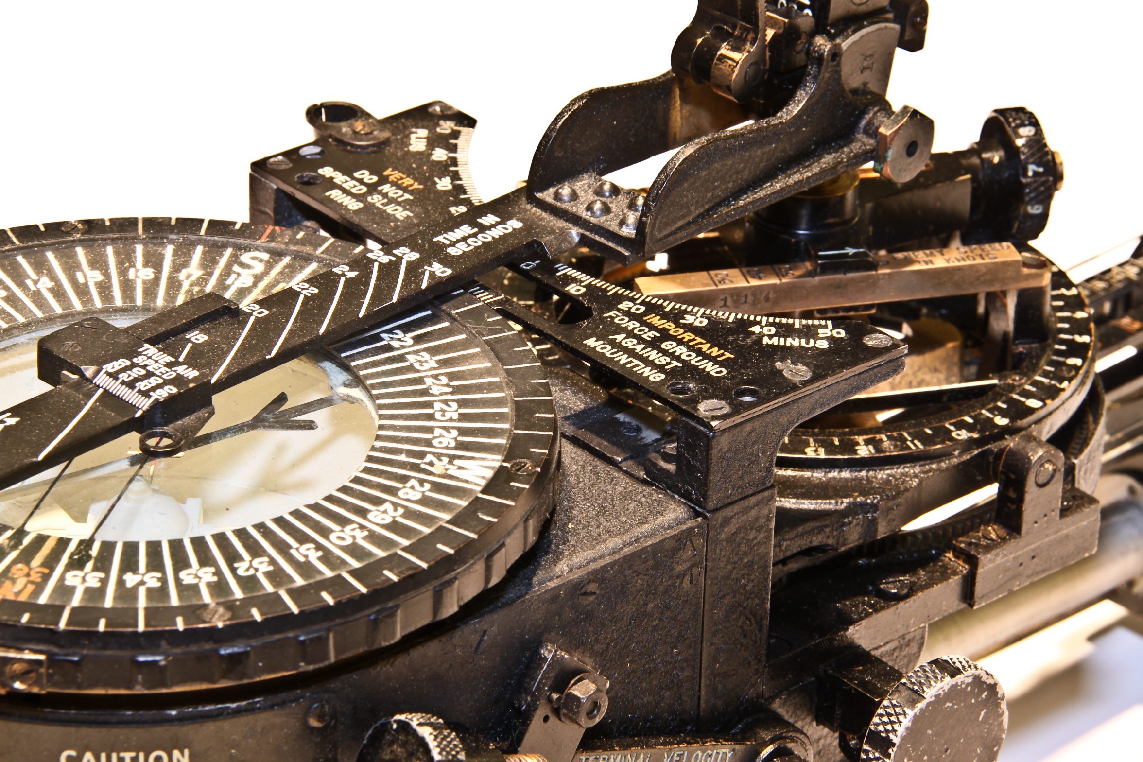
This is a Bendix MG-1 Air Data Computer. It was first used in the F-86 Sabre jet fighter. The F-86 was effectively the first U.S. jet fighter, first deployed in 1949.
I actually have two (slightly different versions) of the MG-1. Figures 1 and 2 show a complete unit. Figures 3-6 show a second unit where I have cut the sealed container to expose the wonderful innards. Inside is a mixture of mechanical pressure sensors (the two cylinders at the top of Figure 3), many mechanical calculating mechanisms, and a number of electrical sensors.
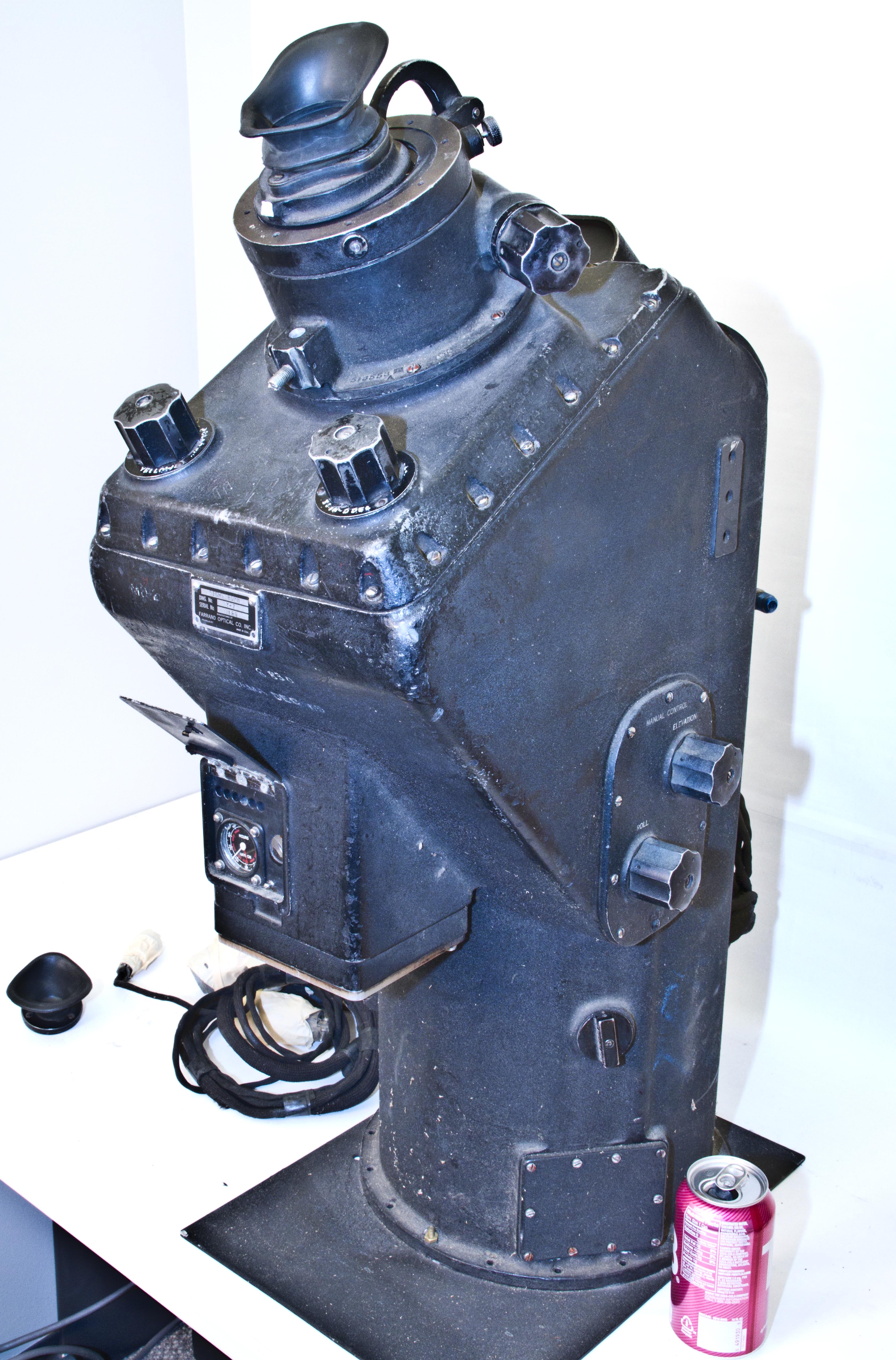
This is another massive optical bombsight made by Farrand. Figure 1 shows the whole 80 pound beast compared to a soda can.
The only reference I can find to it is from the Air Force Systems Command, Historical Publication Series, Development of Airborne Armament, 1910-1961:
The vertical periscopes did not remain immune to the continuing drive for improvement. First, Farrand altered the Y-3 vertical periscope to utilize a shallower optical dome; the revision was designated Y-5, and scheduled for installation in the B-52, Next, the Armament Laboratory published a design exhibit for a 50-inch-long vertical periscope, designated the Y-7, which incorporated the shallow dome of the Y-5. Both Farrand and Eastman Kodak were to manufacture the Y-7. This was the "ultimate" vertical periscope for the "K-Series" system, and was intended for installations in the B-52, the B-36, and the "large nose" B-45. In January 1952 Farrand contracted to design and construct two prototype Y-7's. One month earlier, Farrand had delivered the first model of the Y-5 vertical scope to Boeing's Seattle plant for installation in the XB-52 aircraft.52

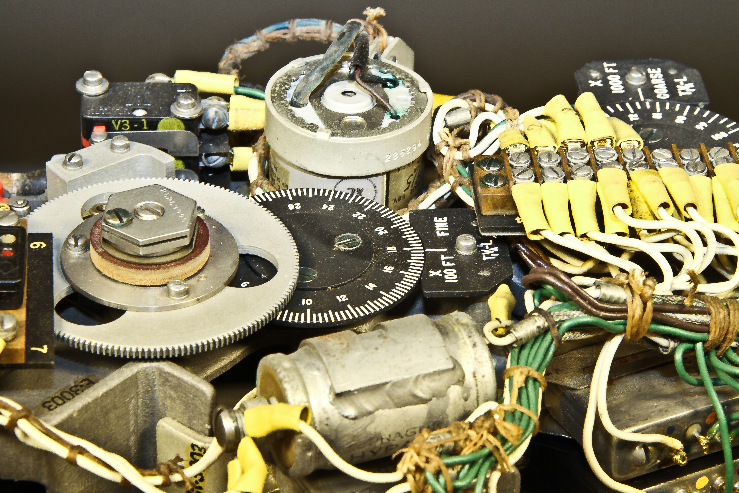
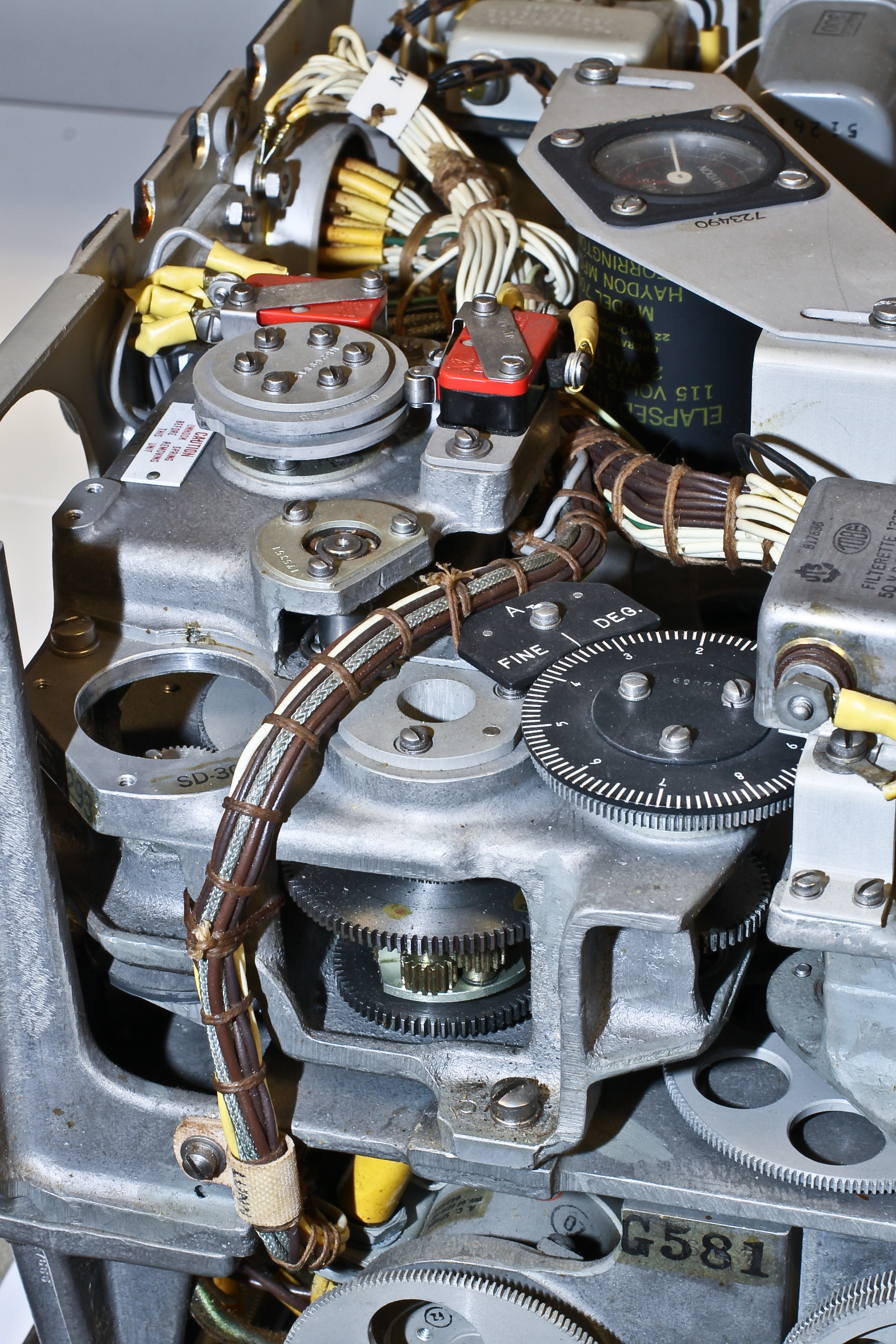
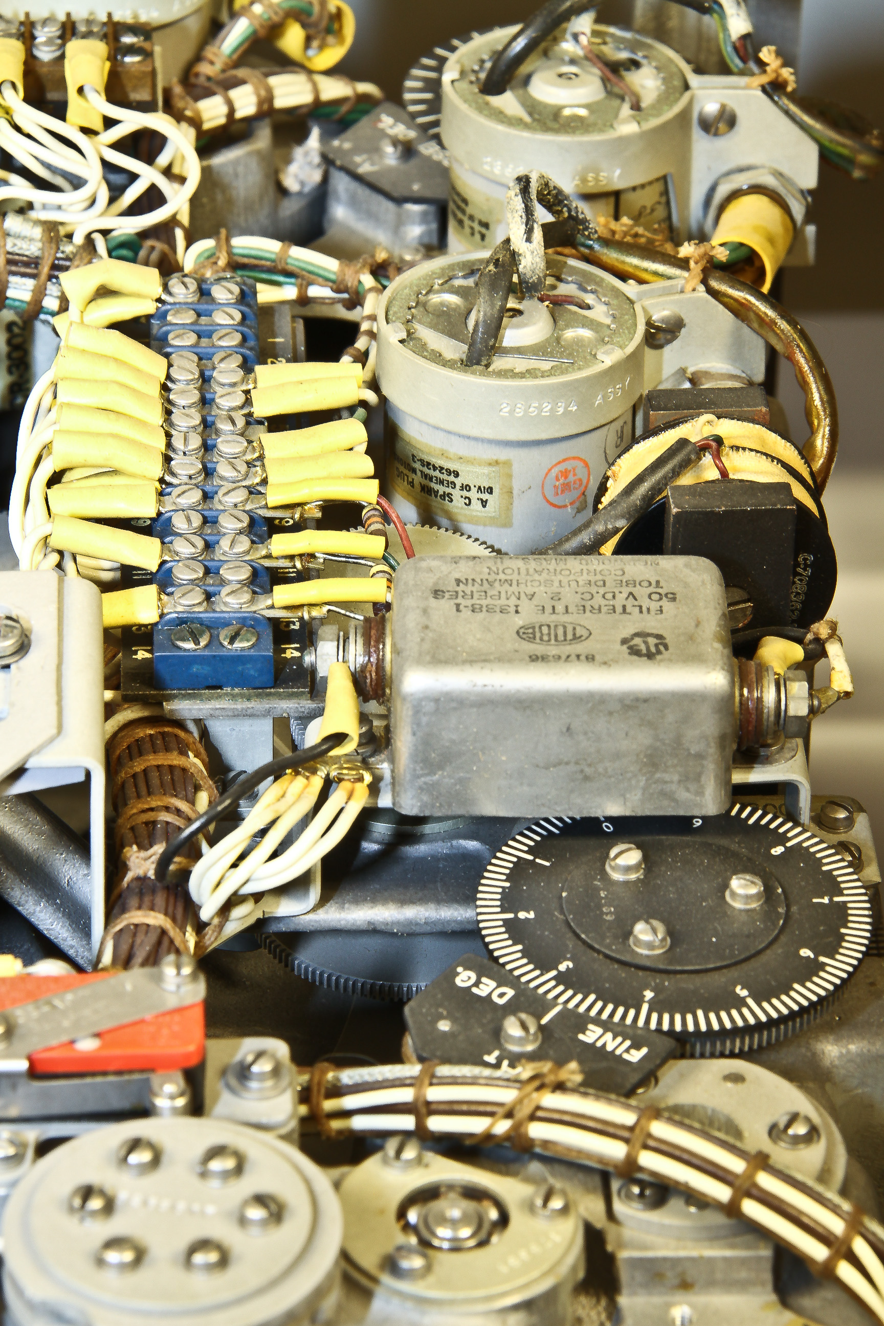
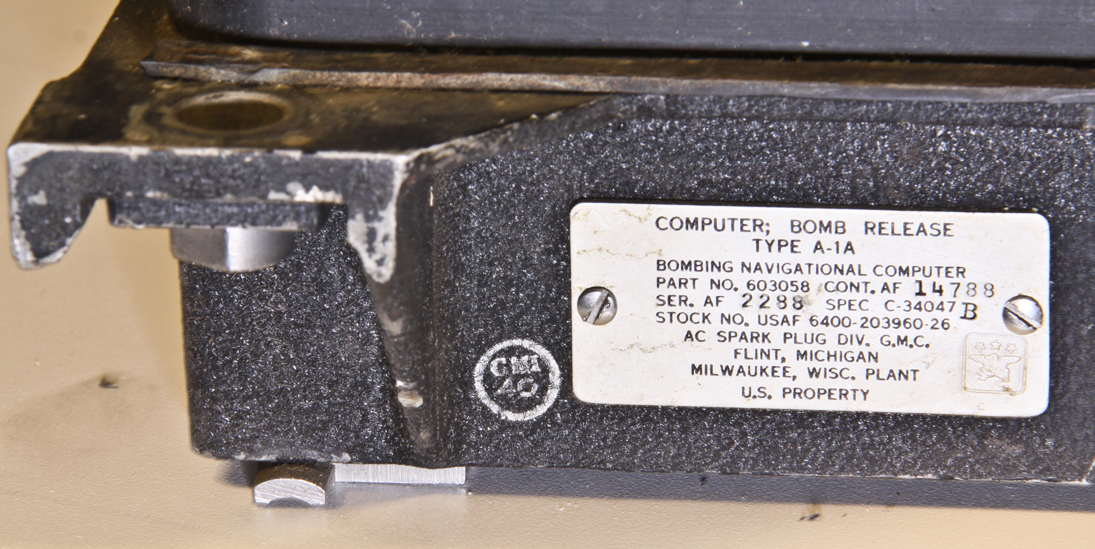
This is a very rare item. It's part of the bombing navigation and control system for the B-36 peacekeeper bomber.
I can find references to the A-1A, but little detail. Here's one reference:
The bombing-navigation system incorporating the Y-3 periscope and the A-1A computer, dubbed the K-3A, came to be the standard system for B-36 aircraft and early production model B-52's.
Another is:
During later modernization programs, the K-1 system was replaced by the much more reliable K-3A system. This included the Farrand Y-3 periscope bombsight, an A-1A improved bombing/navigation computer, and an improved version of the Western Electric AN/APS-23 radar. The Sperry A-1A bombing computer could be used between altitudes of 4700 and 50,000 feet, at grounds speeds between zero and 760 knots.
Note that the Y-3 periscope sight is closely related to the Y-4 periscope sight that we have.
This is part of a complex of devices that integrated navigation, radar, and bombing functions for the giant 10-engine B-36 bomber. We have two components: the APA-59 navigation computer shown here and the A-1A bombing computer.
Figure 4 is a picture of the navigator/bombardiers station in the B-36 showing a very recognizable APA-59 (outlined in red) just beyond the bombsight periscope.
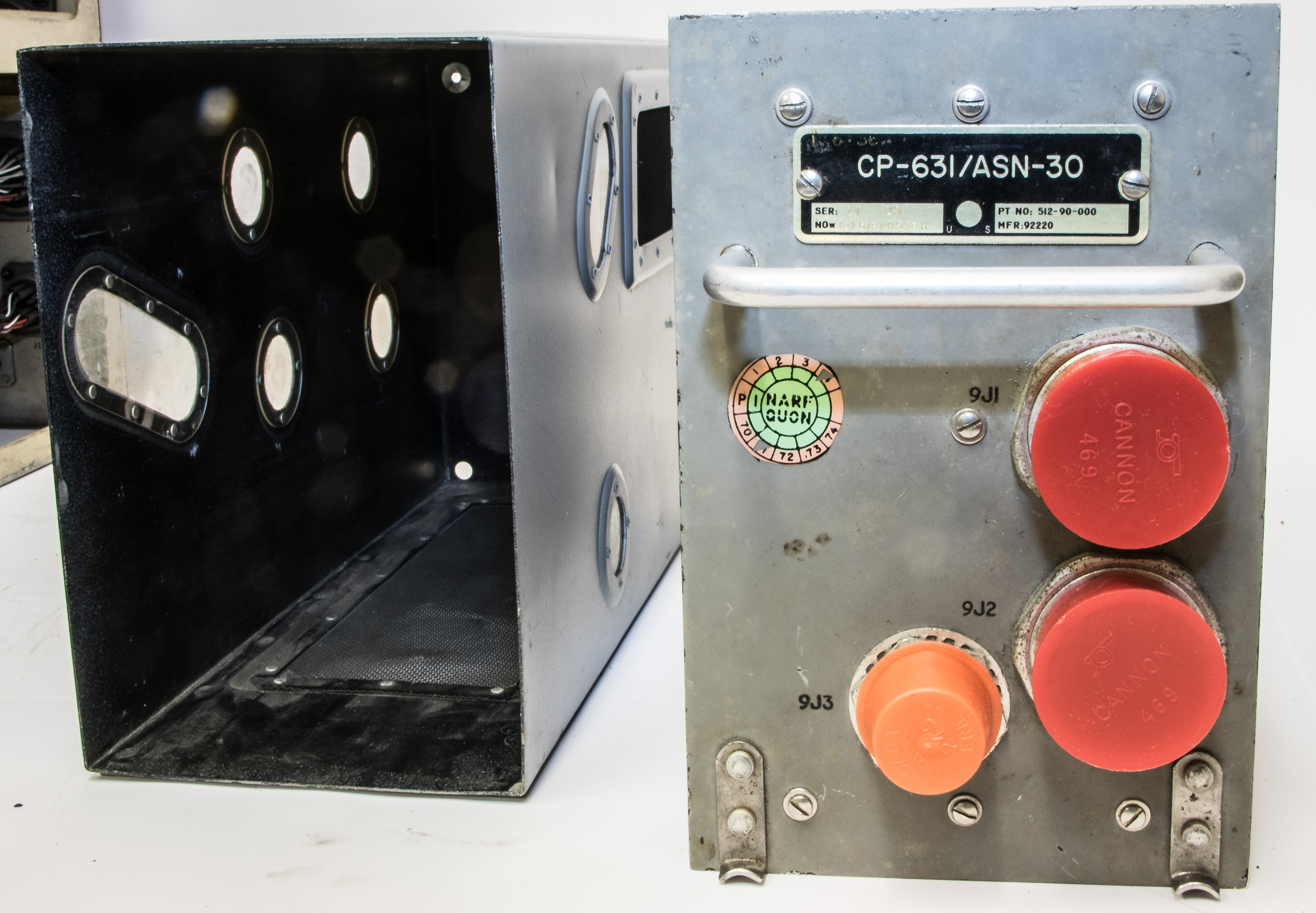
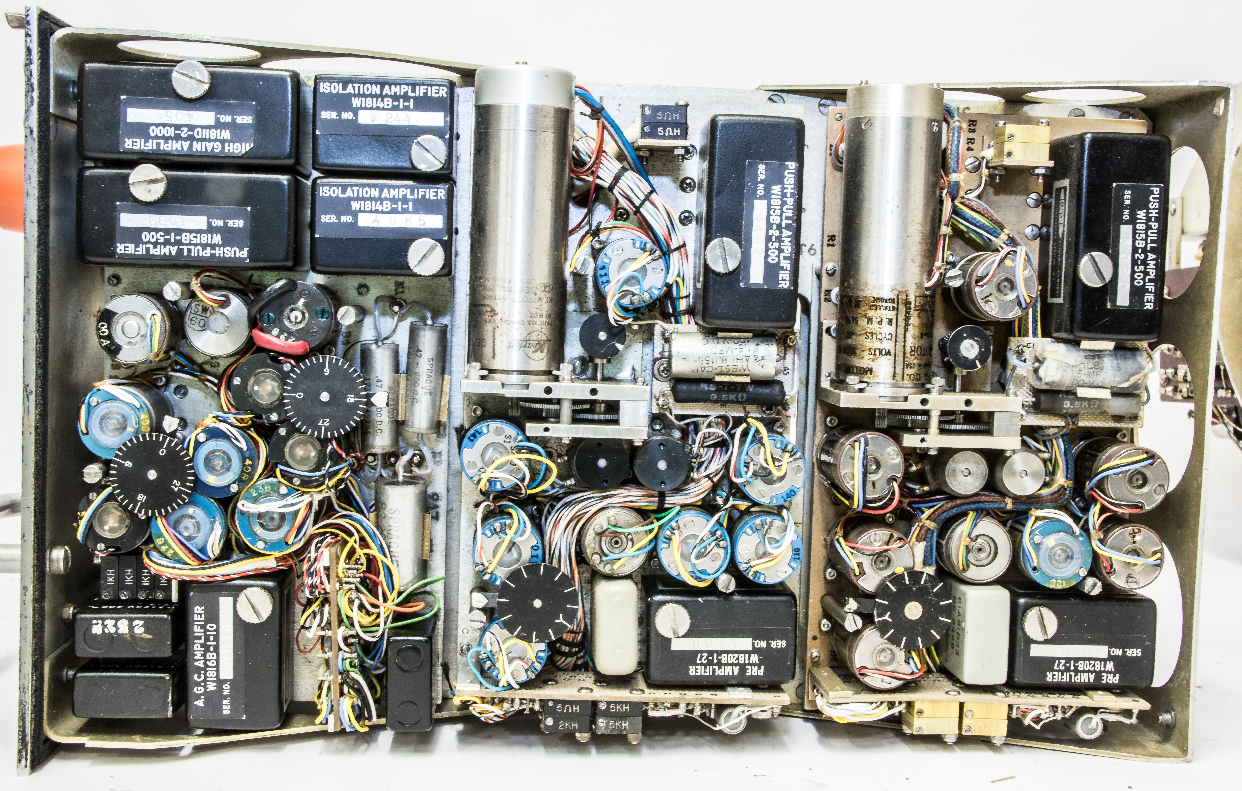
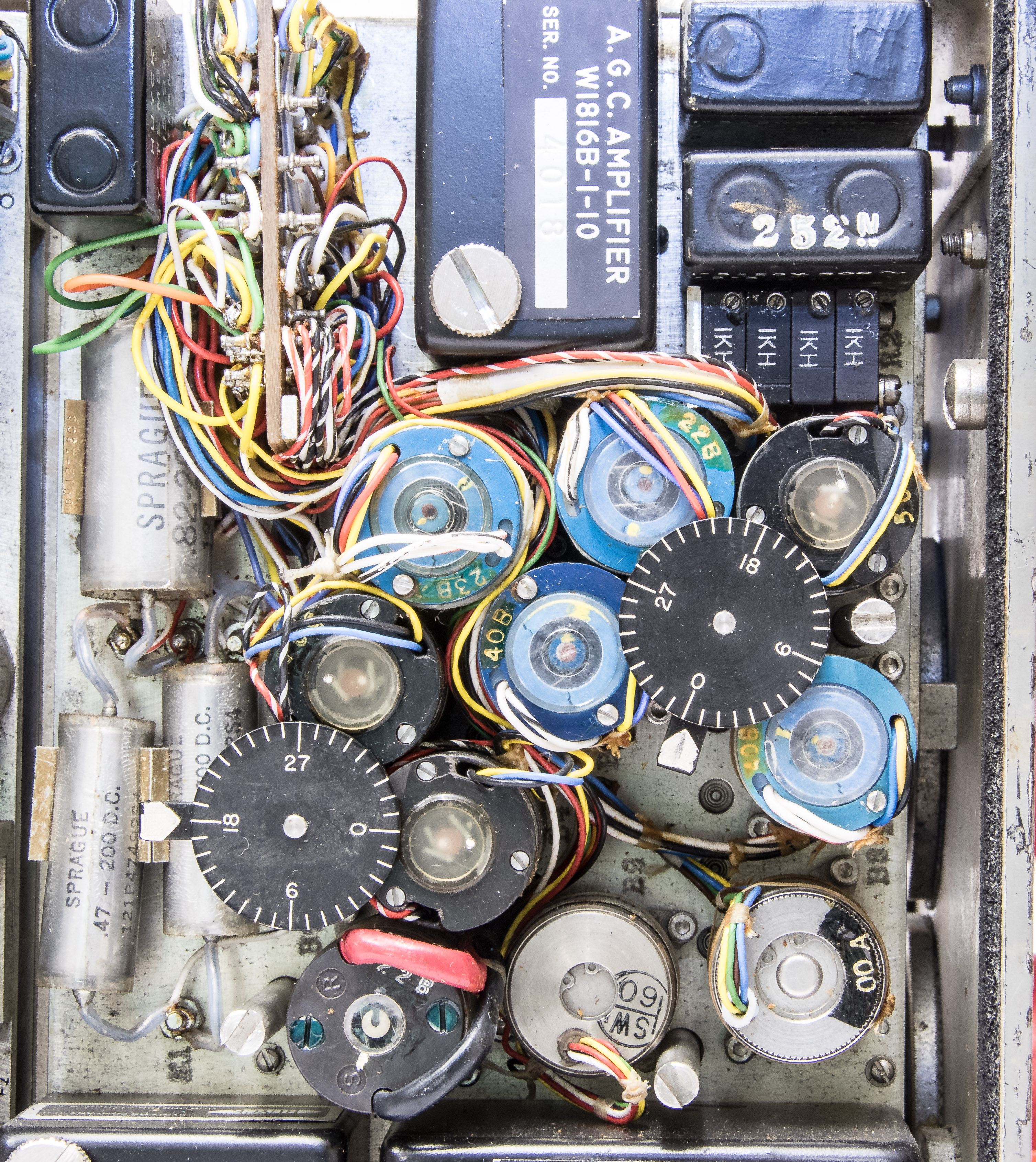

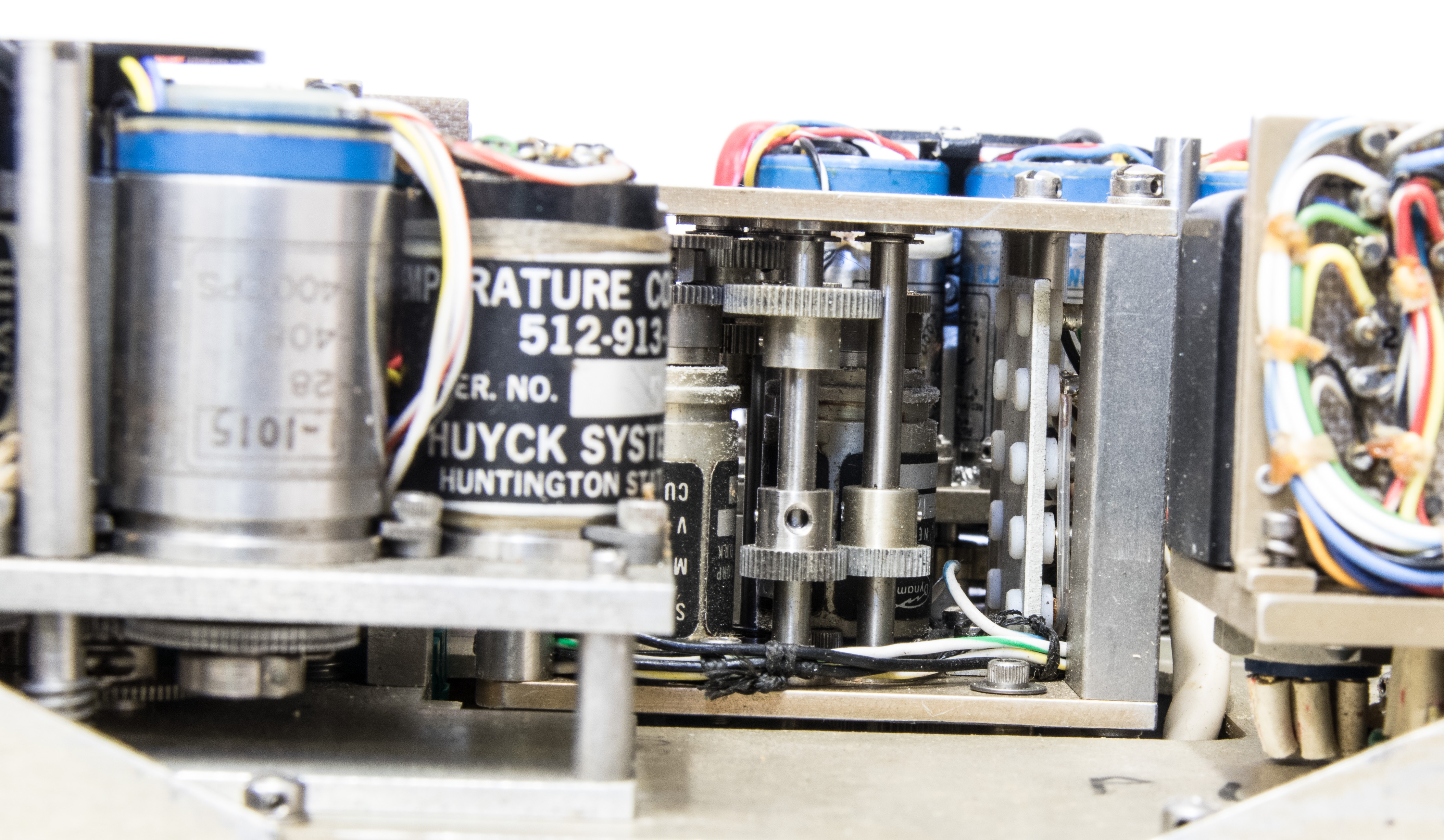
This is the CP-63 analog computer component of the AN/ASN-30 Anti-Submarine Tactical Navigation System (ASWTNS). It was used on an Grumman S-2 Tracker ASW (Anti-Submarine Warfare) aircraft, which entered service in the 1952 as a carrier-based plane. The ASWTNS was an electro-mechanical navigational and tactical computer and display system designed to solve ASW plotting, display and tactical co-ordination problems. It utilized both automatic and manual inputs to compute and display solutions to both navigation and tactical ASW actions.
This is the stabilizer component (i.e. gyros) from a "Horizontal Periscope Bombsight, Type B-1" made by Sperry. Note the resemblance to the name of the B-47 Y-4 "horizontal periscope bombsight" in the above topic. Perhaps this was the corresponding gyro unit for the B-47. Beyond this speculation, I can find references to the fact that the the USAF used a B-1 bombsight, but can't identify where it was used. Our device was last serviced in 1956, but the B-1 wasn't withdrawn for USAF procurement until 1974.
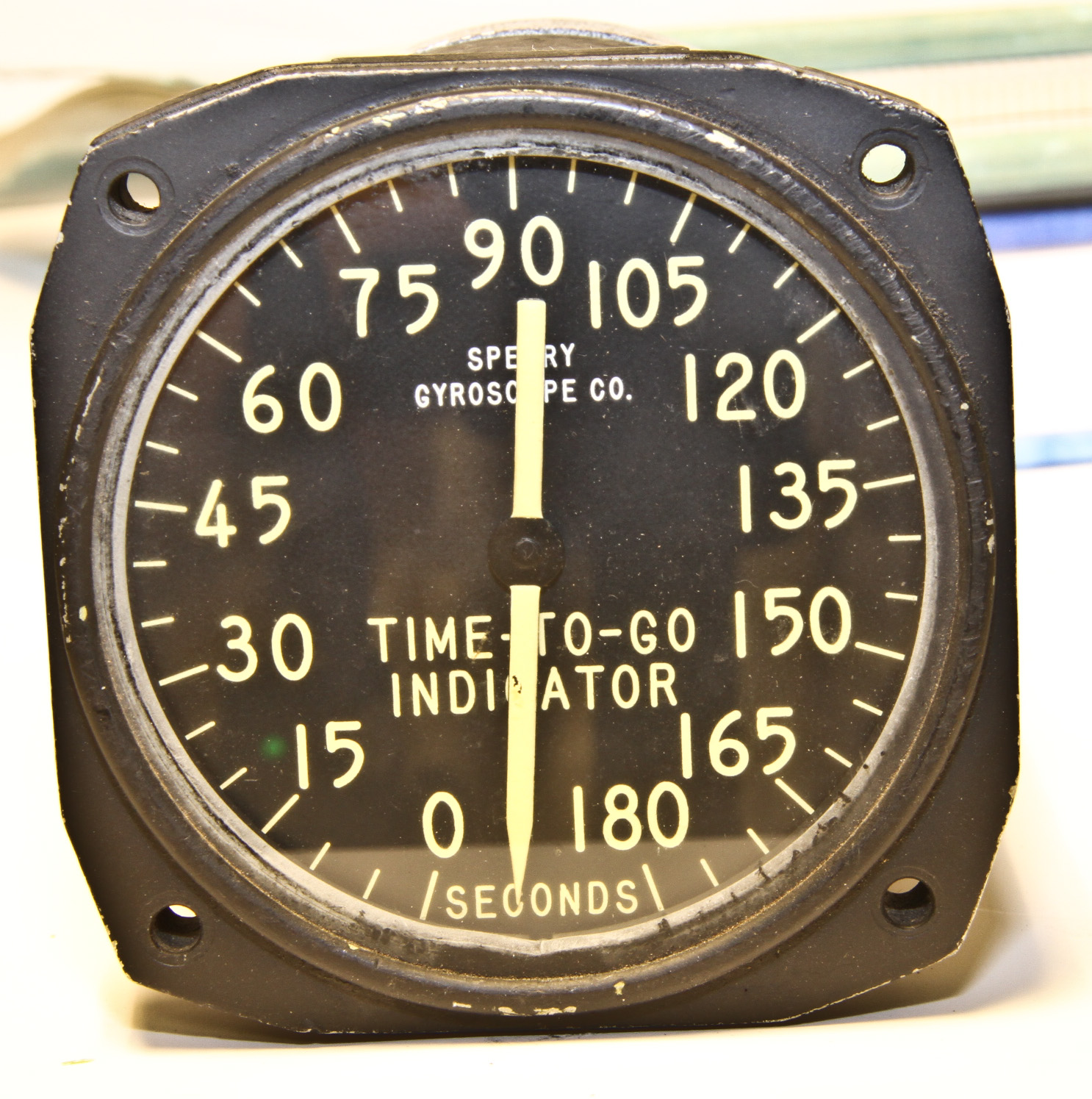
I also have a "time-to-go" indicator instrument used with "B-1 Bombing Navigation Computer." This is more evidence that the B-1 bombsight existed.


The M1 Toss Bomb Computer seems to have been used on the Canberra B-57 bomber, but I can find little documentation about it. We don't have the computer itself, but do have its cockpit control panel and its gyro.
Interestingly, it seems to be the subject of a patent suit between the manufacturer of our devices (Mergenthaler) and SAAB. Figure 5 shows the first page of the Mergenthaler patent (filed 1961). It contains a good explanation of the physics of toss bombing and how the appropriate calculations could be done using 1960 technology.


This is a "torpedo director" used on the WW II Douglas A-20 bomber. According to the Douglas A-20 Havoc Pilot's Operating Instructions (which we have), a torpedo director "is an instrument operated by the pilot to help him approach a moving target in such a manner that the torpedo will intercept the target on its course." The computation mechanism of the B-2 is simple, but it does compute in a way. On the right is the first page from the 1945 patent for the B-2, which describes the operation of the B-2.
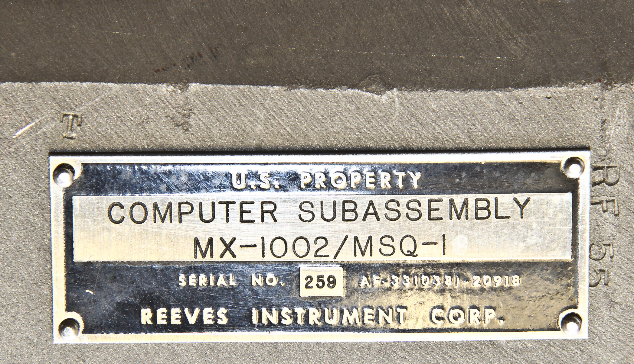
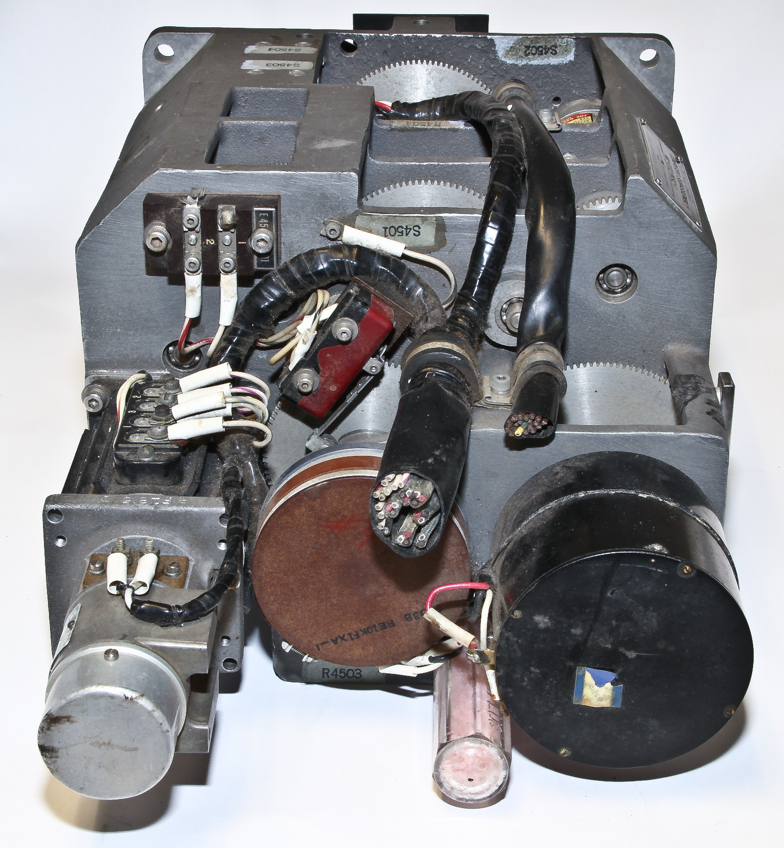
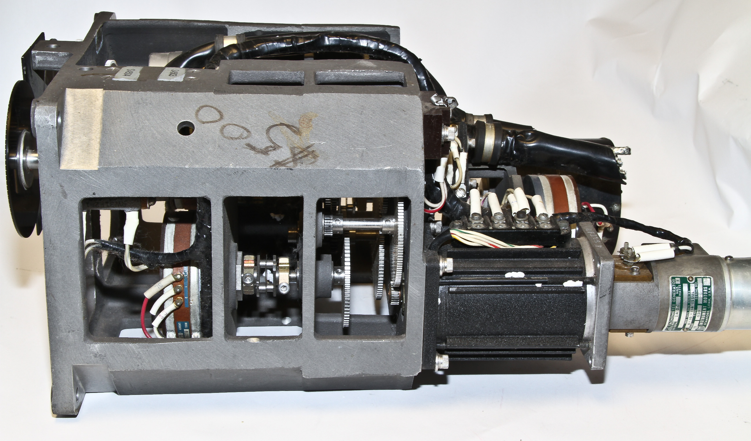
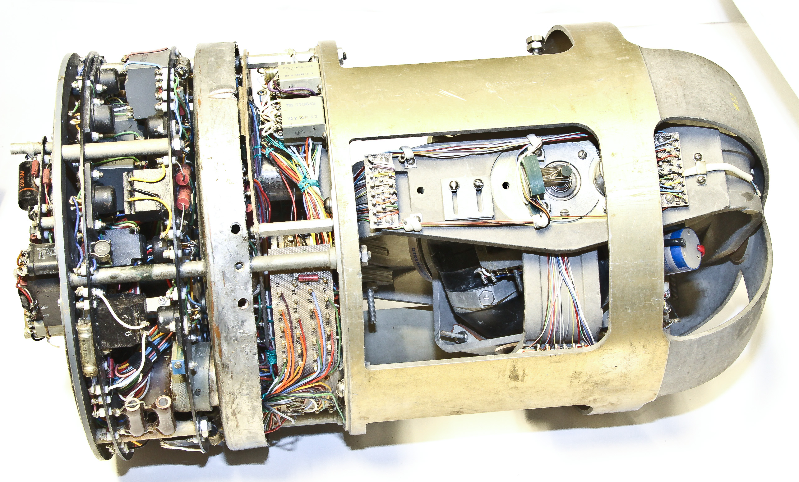
The MSQ-1 was a 1950's era radar tracking system used in the control of Matador surface-to-surface cruise missiles. Our subassembly is clearly part of the tracking display system. It is interesting because of its robust design; it is clearly designed for heavy duty use in high shock environments.
This is yet another not-a-computer, but it is interesting. It's a compact 3D gyroscope obviously used in some inertial navigation system. Its cylindrical shape (about 9 inches in diameter and 16 inches in length) suggests that it came from a missile of some sort. It is heavy for its size, about 30 lbs.
The block cylinders within the gimbals in the closeup pictures are the gyros. There are two pairs of them mounted at right angles to the other pair.
There are no identifying labels that I can find, but the last service sticker was from 1961.
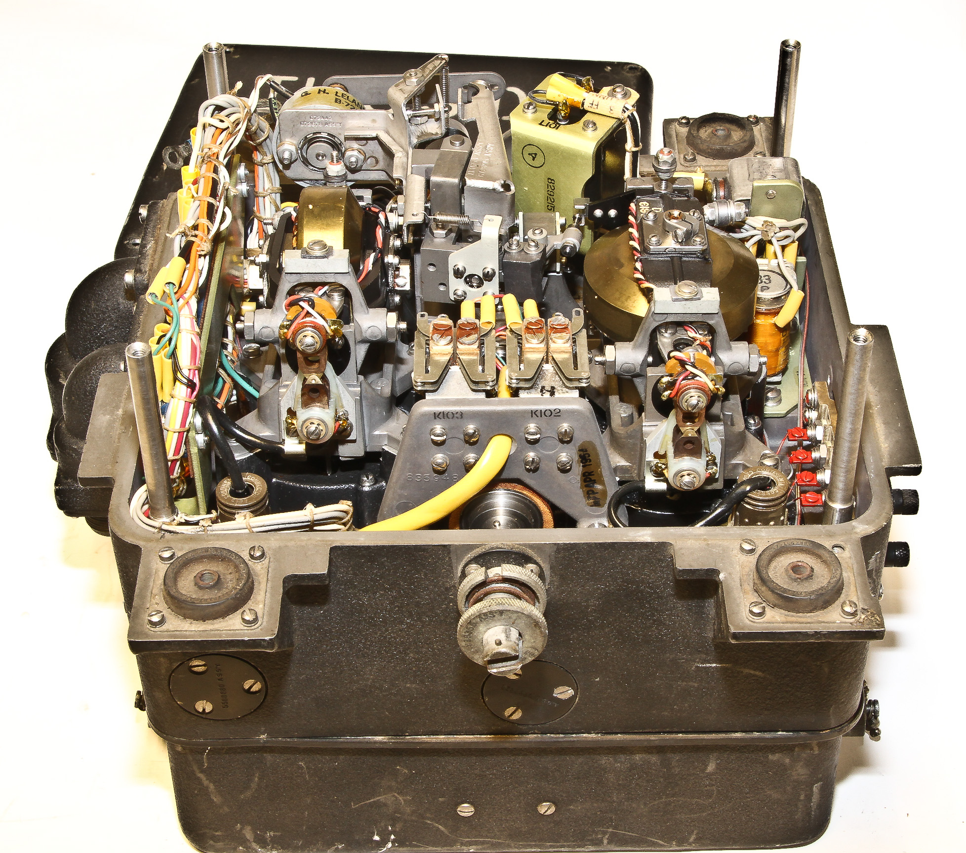
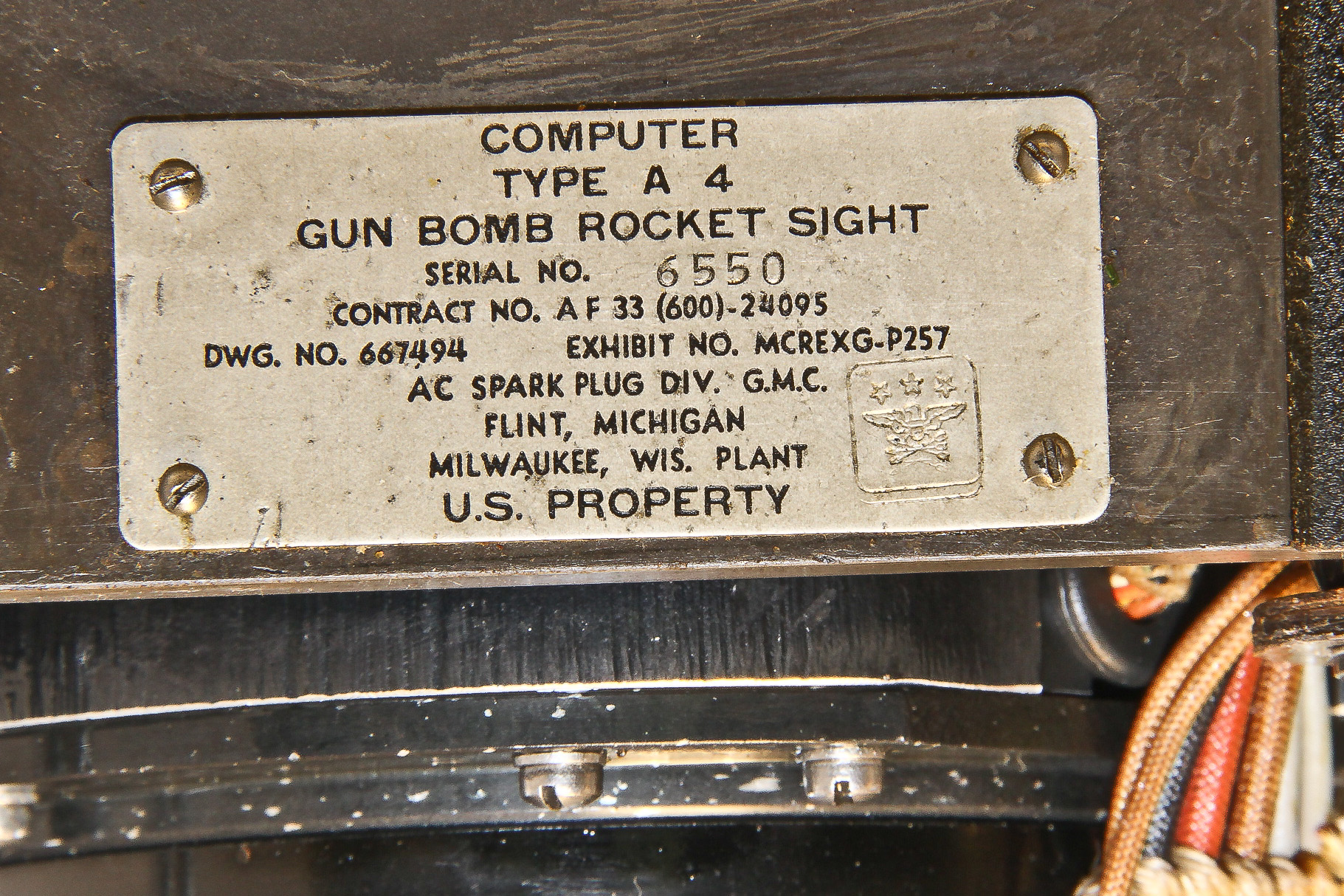
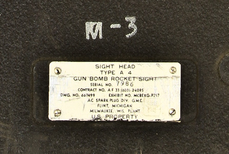
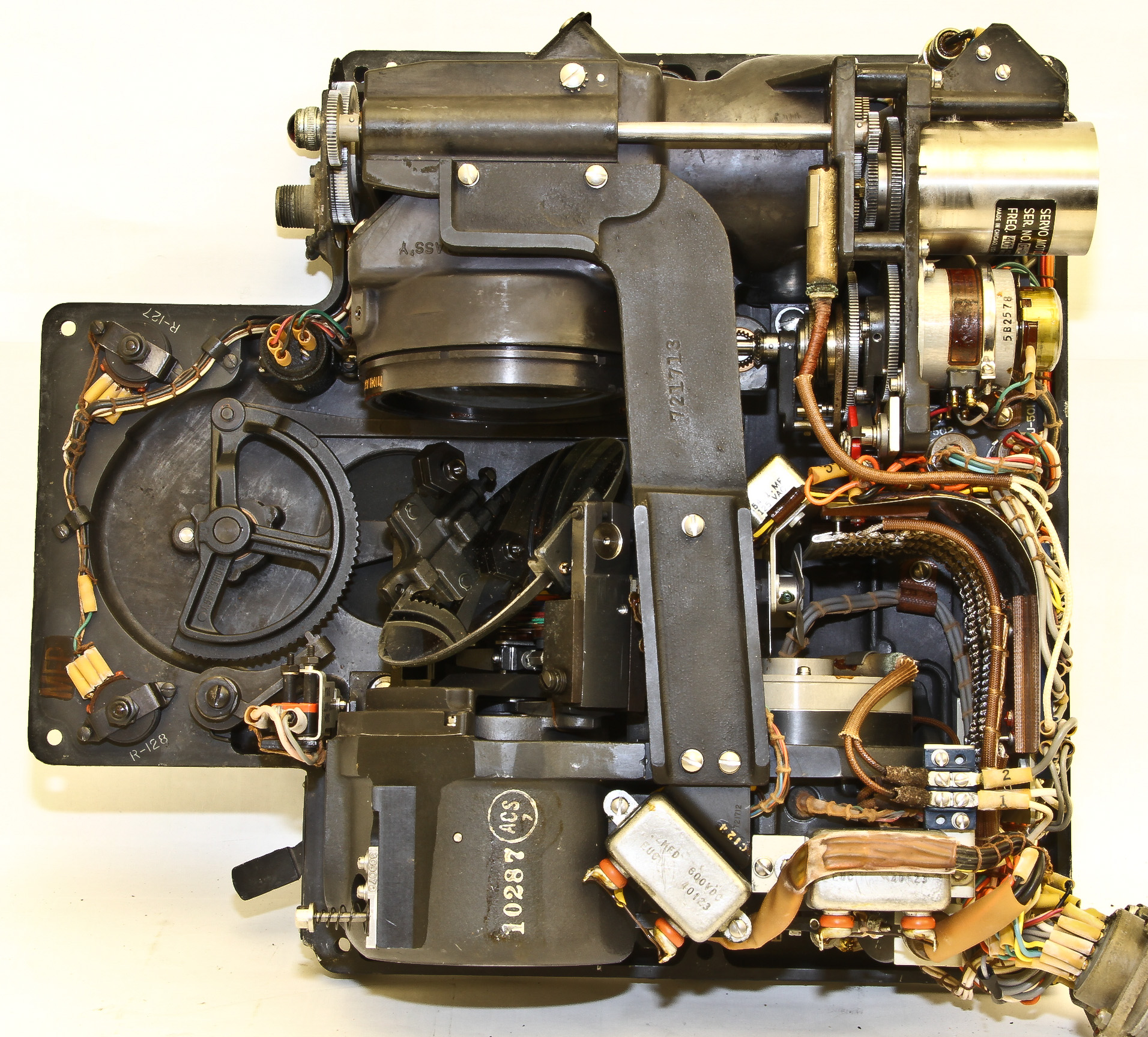
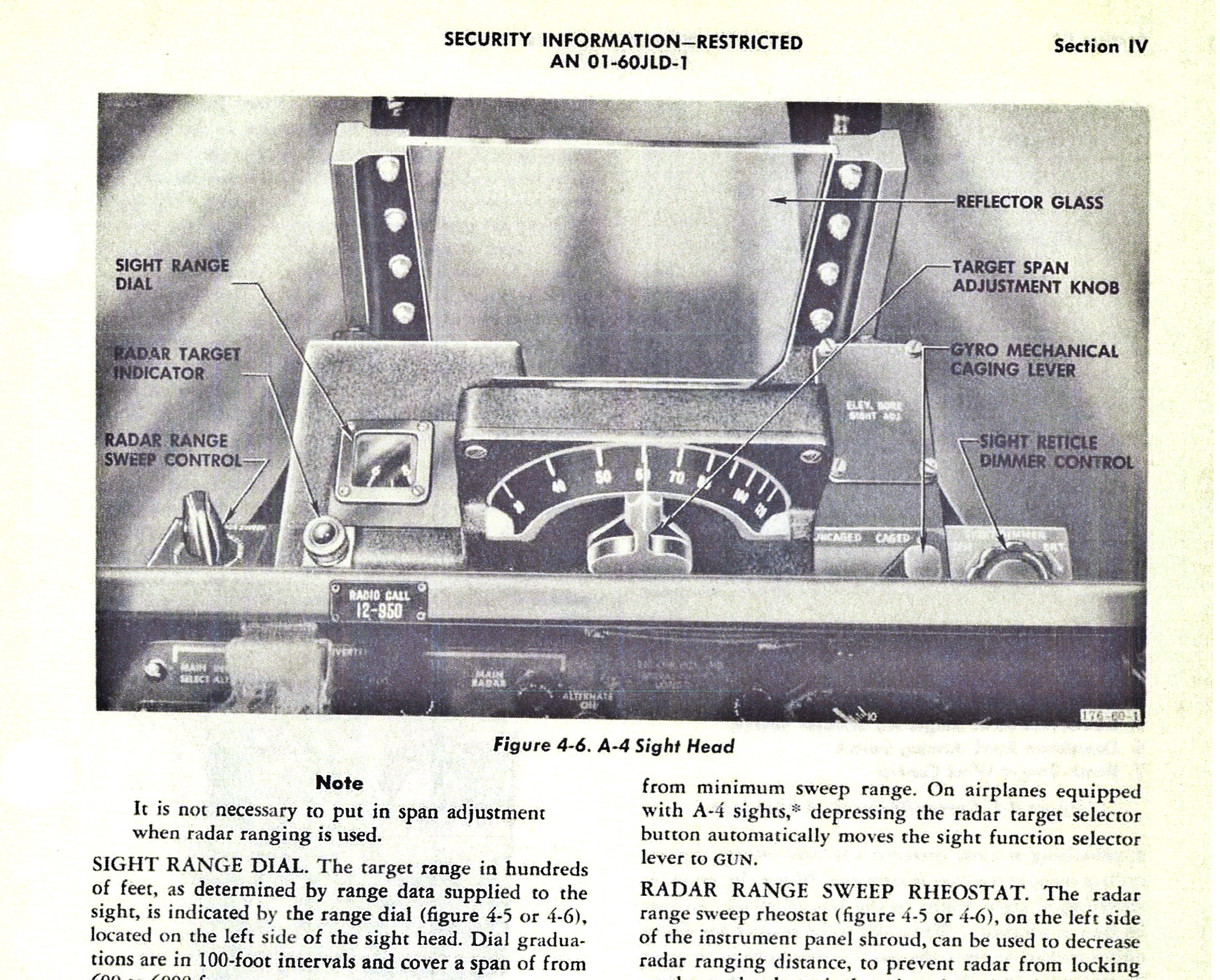
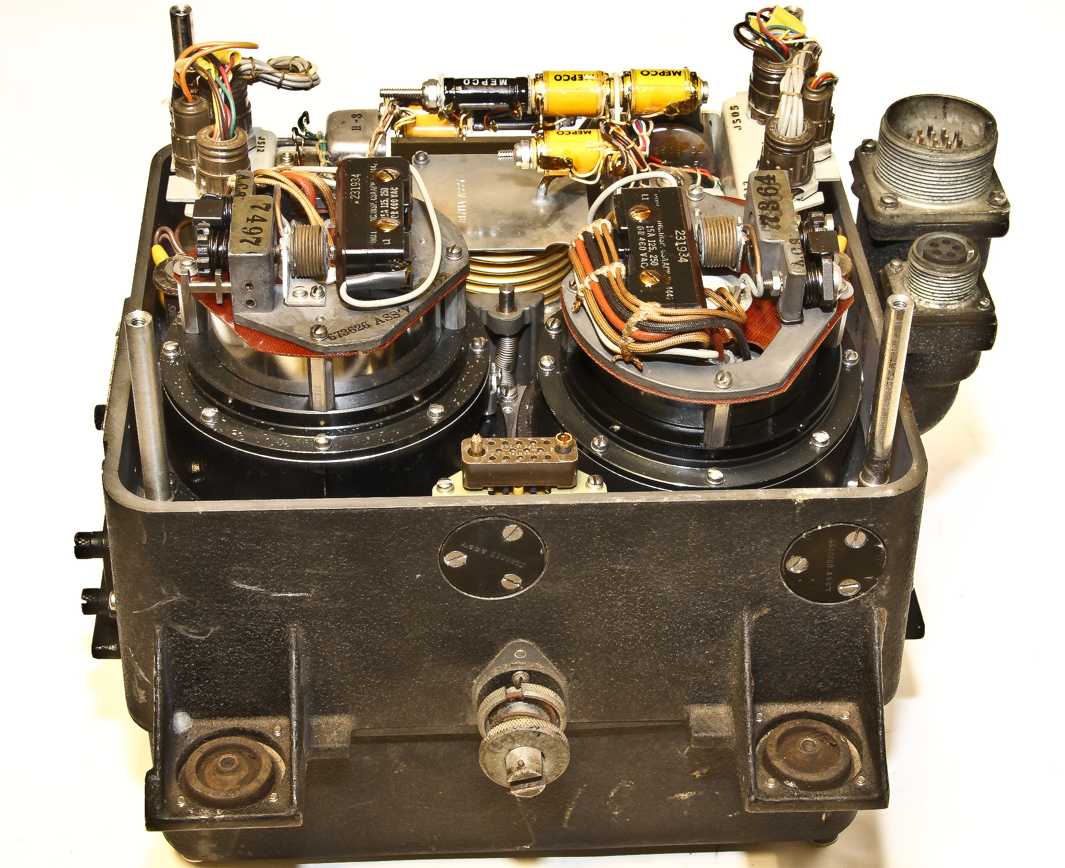
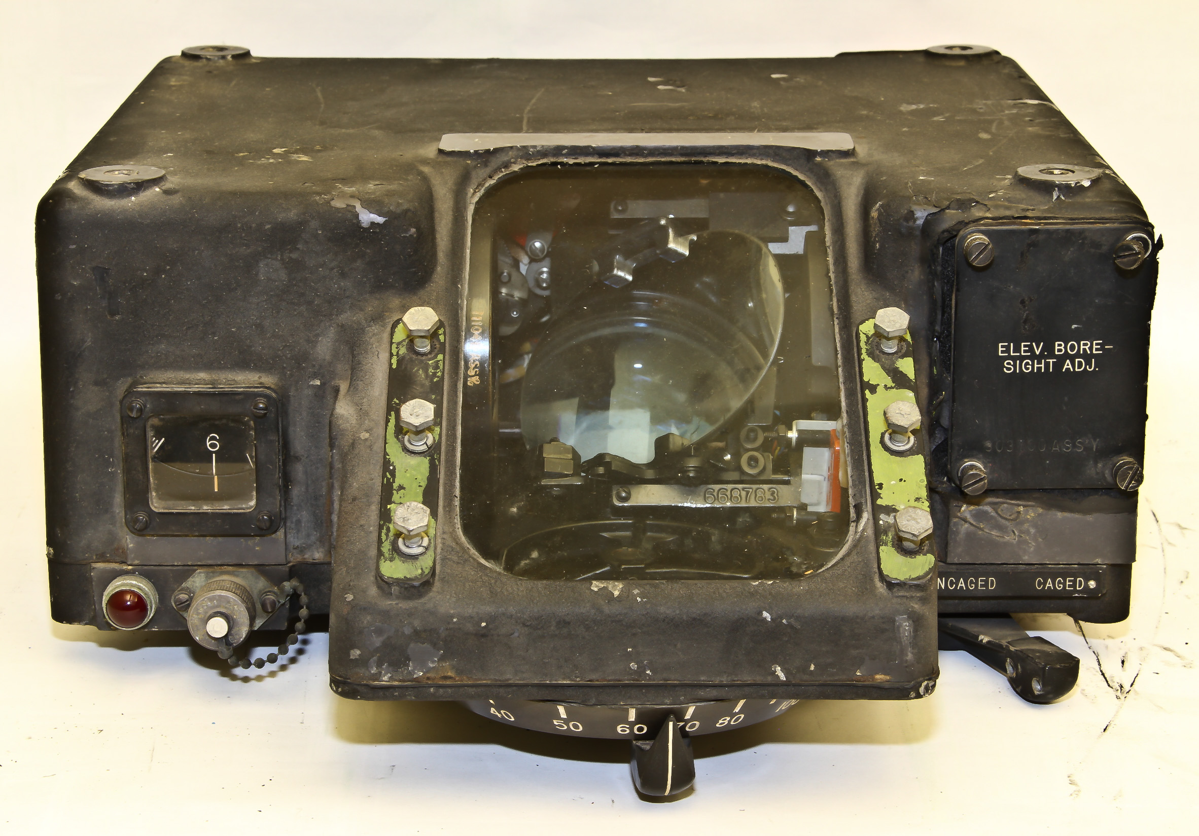
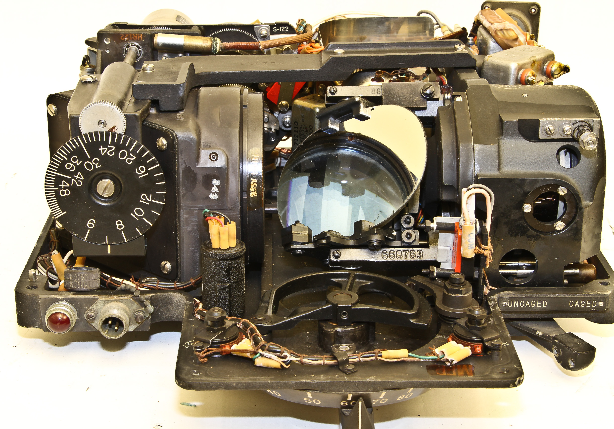
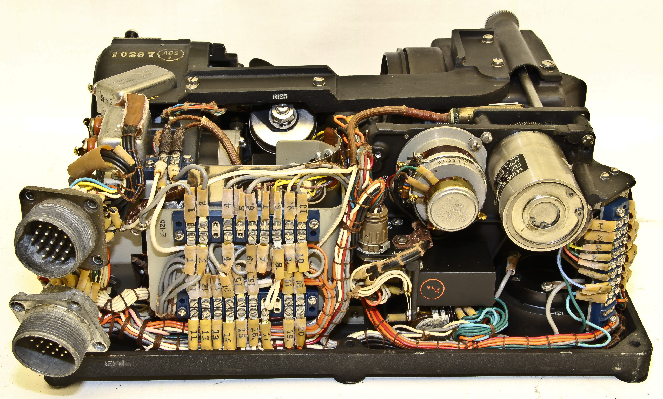
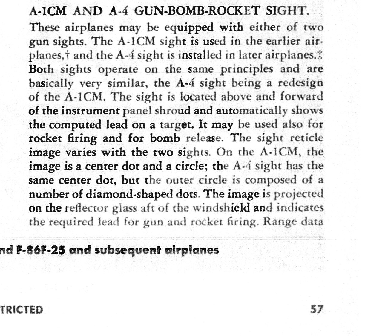
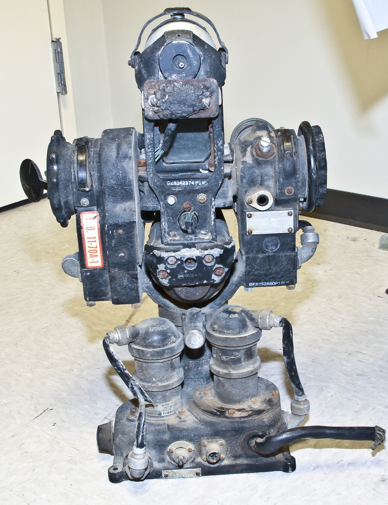
This is the sighting element and the computing element of the gun/bomb/rocket aiming sight used on F-84 Thunderjet and F-86 Sabrejet fighters. Figures 1-3 show the computing element, and Figures 4-9 shows the separate sighting element. Figures 10 and 11 show information about the A-4 from from an F-86 flight manual.
In the back of the dusty museum I found a pedestal gunsight from a B-29. This sight was in the left or right rear sighting blister of a B-29 and was connected to a B-29 fire control computer (the previous museum entry).
Our sight is in bad shape and I've done nothing (yet) to restore it. However, you can definitely see recognize it from the drawing of a B-29 pedestal sight from the Gunner'S Information File>.
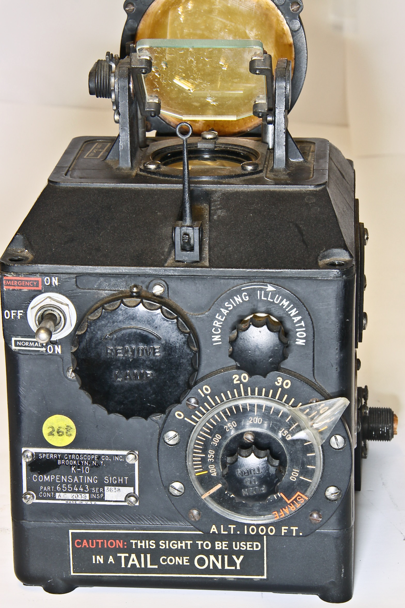
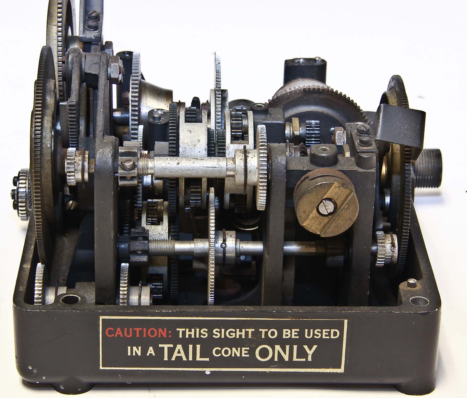
Here is a K-10 Compensating sight with lots of detail about its simple computing element. It is particularly interesting since it makes extensive use of cams, which are an analog version of a ROM. In particular, its has two two-dimensional cams, one of which drives the axial position of the other. In the top right picture one of two cam followers stick up which drive "logic" above this assembly.
The Sperry K-9 is a computing gunsight used in Marin upper gun turrets on the B-26 and B-24 bombers. It operates similarly to the Sperry K-3 except that the computer is fixed and gets information from a separate movable sighting head.
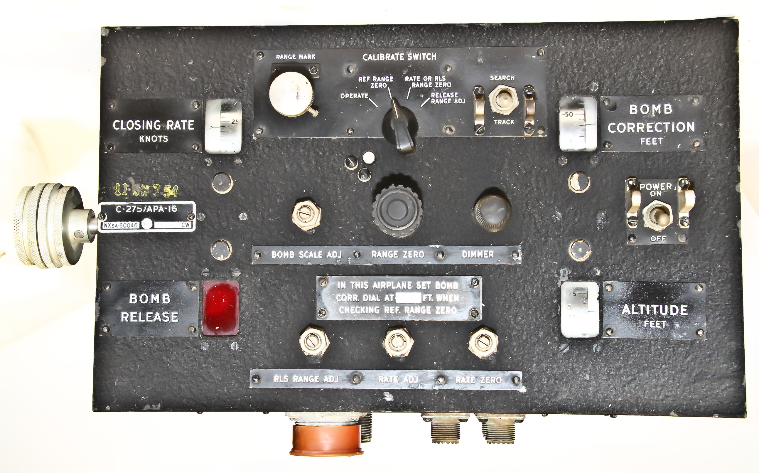
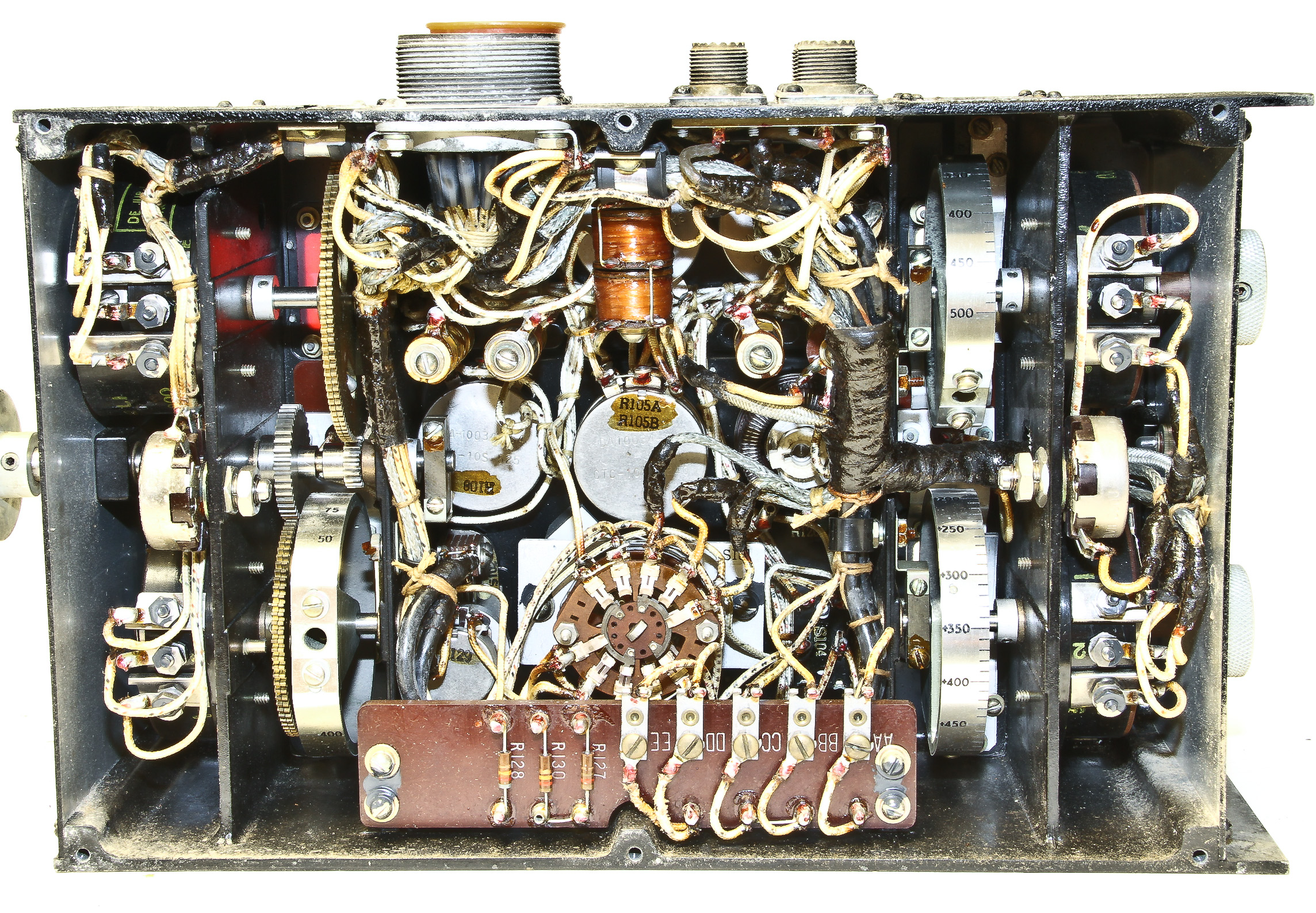
This appears to be the control console for an AN/APA-16 radar bombsight. It was used in the World War II era PBY-6 patrol bomber.
Actually, I'm not sure what this really is. In the military's AN classification scheme, it falls between ASA-23, a "Missile Launching Set", and ASA-25, a "ASW Data Display Group".
This is the control panel for the nose gun of a B-36. It is similar, but slightly different to a control panel for the tail gun on a B-47. Figure 2 shows the B-47 panel in a B-47.


This is a fairly common WWII-era gyro gunsight used by the US Navy.
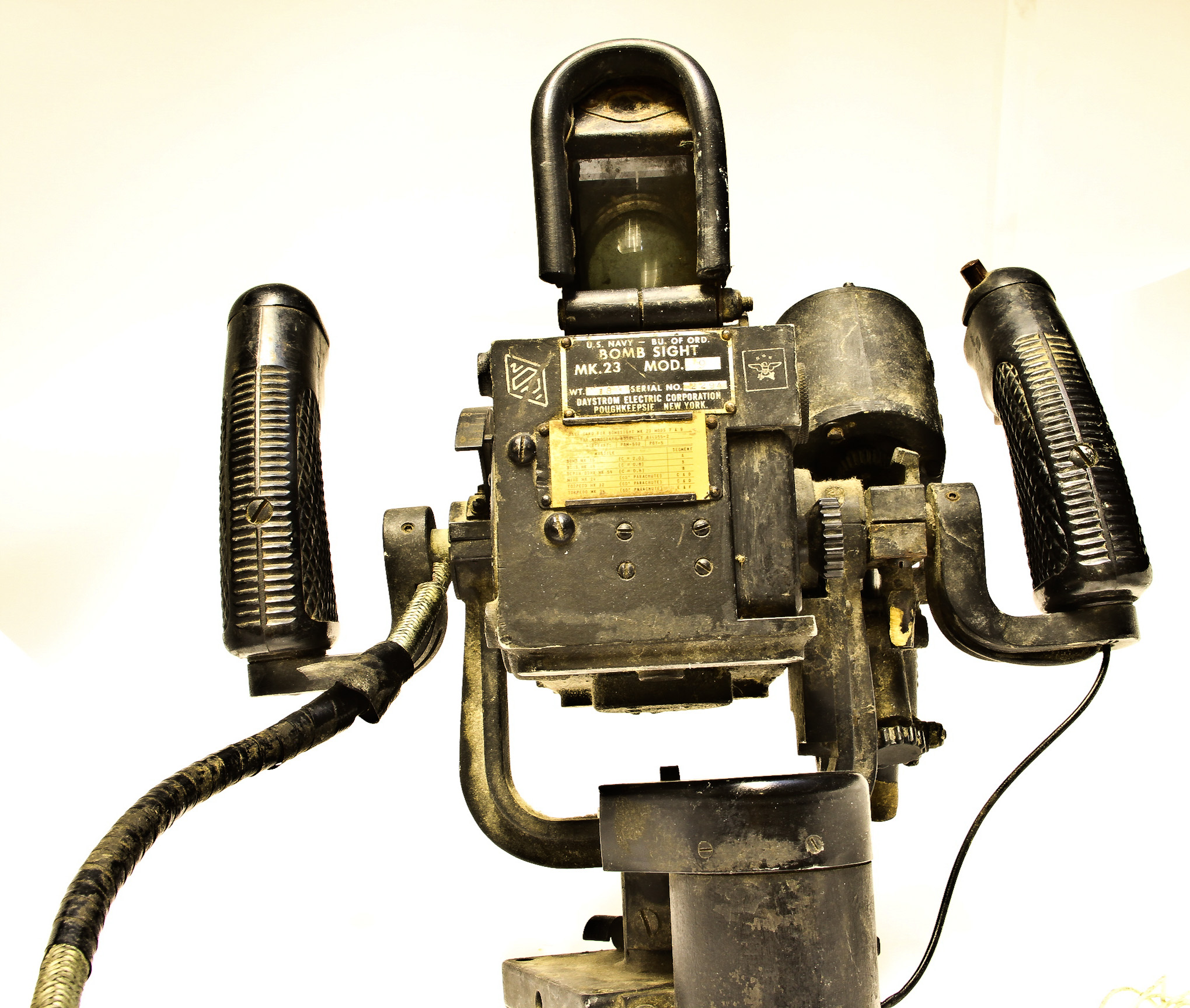
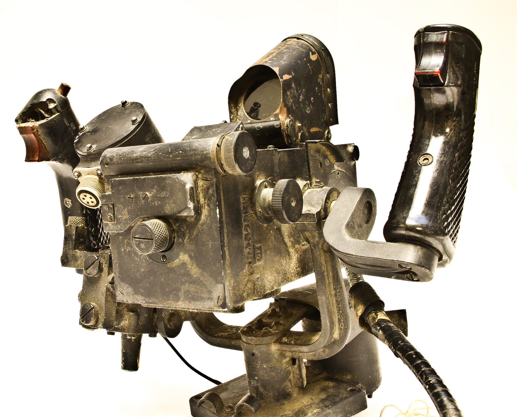
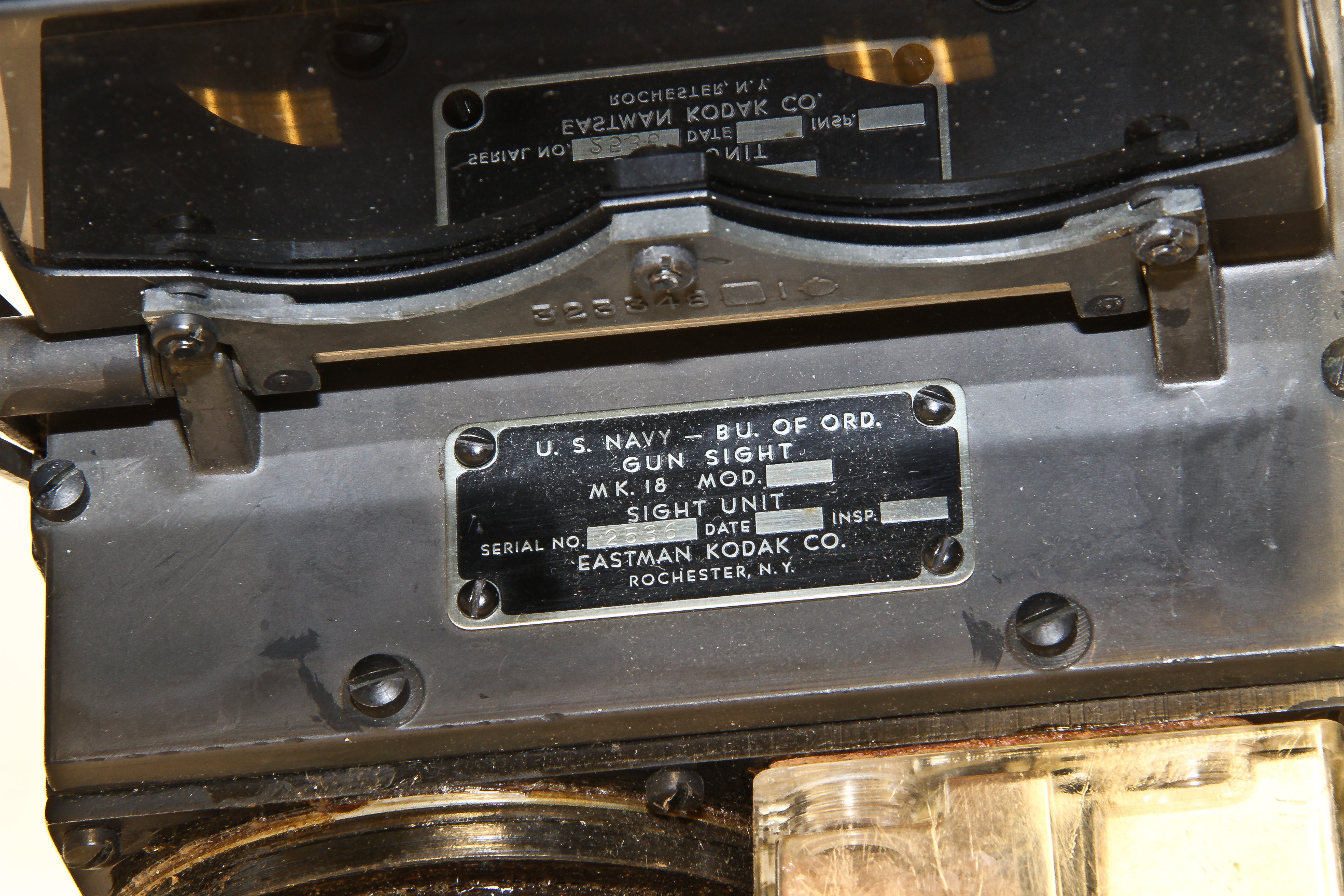
This is the sighting component of the Mk23 bombsight. I know little about this device other than I think it was used on the P2V Neptune antisubmarine plane.
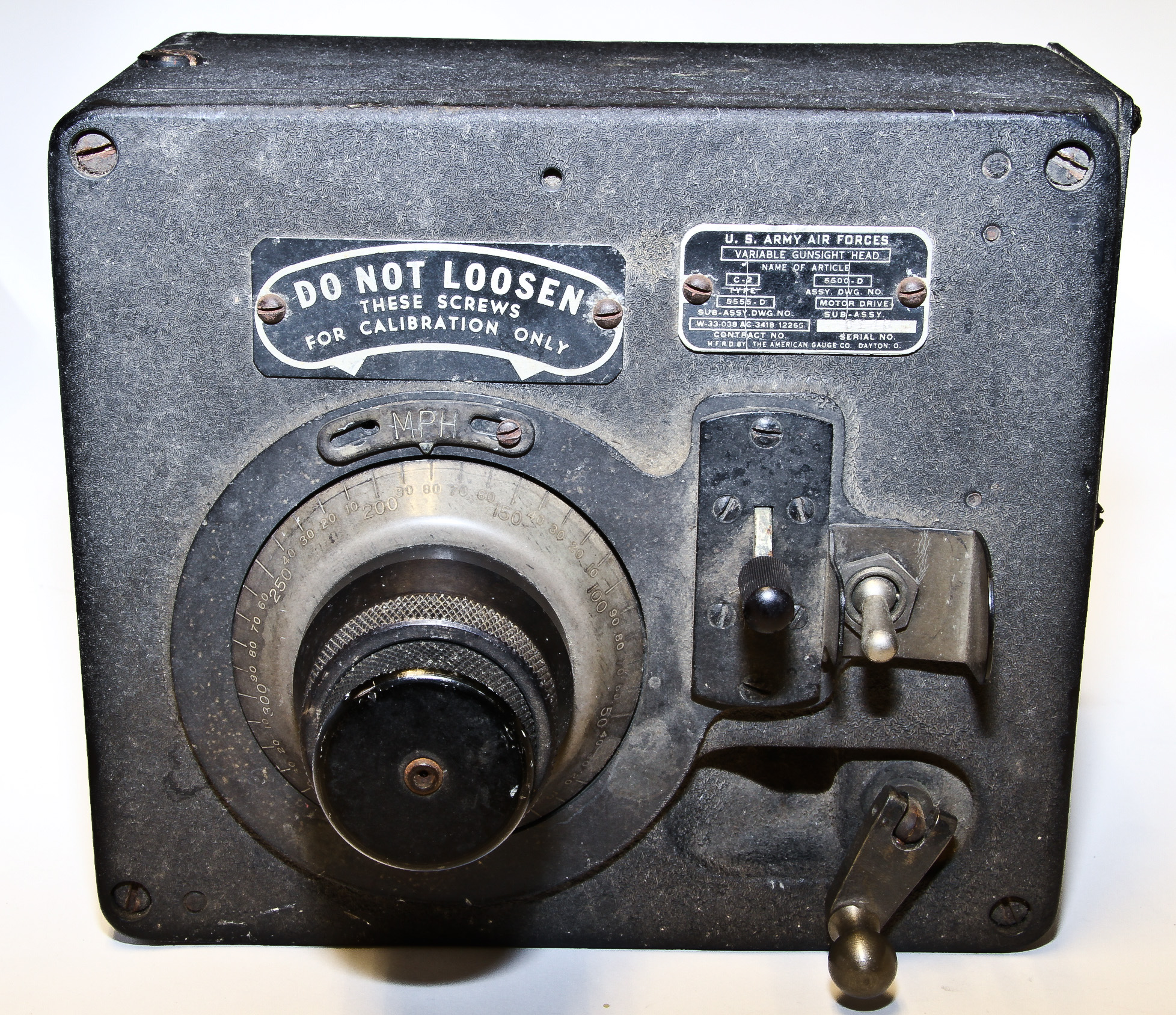
Actually, I'm not sure what this really is, other than what it says on the label. Yet another mysterious piece of military equipment.